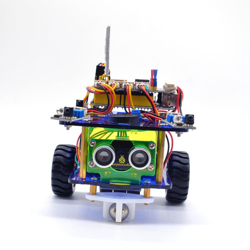
OpenELAB Desktop Mini Bluetooth Smart Robot Car Kit V3.0
Product Link
Description
We can often see others on the internet making use of control boards and electrical components to build their own creative robots. Wanna DIY your own robot?
Here comes OpenELAB desktop mini Bluetooth smart car V3.0, which is an upgraded version of OpenELAB desktop mini Bluetooth smart car V2.0.
The smart car still keeps the functions like line tracking, obstacle avoidance, IR and Bluetooth control and more.
Furthermore, we make a great improvement for the smart car as follows:
The Acrylic plates are more bright and colorful;
Adding a microphone sound module to make a fantastic sound when driving the car running;
Using Bluetooth HM-10 module,which can support Bluetooth 4.0; supporting both Android and iOS system; also can actuate the smart car with our own designed Bluetooth APP.
Can freely choose the battery case 18650 or 4-cell AA battery case to supply power for the robot car. Note that batteries are Not Included. Users can freely choose two 18650 batteries or four AA batteries (1.5V) to supply power for the robot car.
Making improvements on the motor drive board; one is coming with a slide switch for controlling the power switch;the other is adding 8 jumper caps to control the DC motor direction by hand,easy for code debugging.
Coding the robot car with Mixly blocks software, more simple and ready to play.
From the basics up to complex projects, through this kit you can learn to control the robot car with Mixly blocks coding. Easy to code and learn coding and computational thinking.
If you are looking for inspiration, you can find a great variety of tutorials here. Take your brain on a fun and inspiring journey through the world of programming and electronics.
Parameters
Motor Voltage range: 1-6V; motor shaft length: 10mm; speed: 6.0V 100rpm/min.
Motor control is driven by L298P;
Three groups of line tracking modules, to detect black-white line with higher accuracy and can also be used for anti-fall control;
Two groups of obstacle detector modules, to detect whether there are obstacles on the left or right side of smart car; Ultrasonic module is used to detect the distance between ultrasonic and obstacles, forming the smart car’s obstacle avoidance system;
Bluetooth wireless module can be paired with Bluetooth device on mobile phone to remotely control smart car;
Infrared receiver module is matched with an infrared remote control to control the smart car;
Can access the external 7 ~ 12V voltage.
Component List
When get this smart car kit, at first glance, you will see the beautiful packaging box. And each component is safely packed inside the small bag in order. You will get such a bulk of components and screws to make your own smart car. So we have listed all the components as follows:
Components
Quantity
Picture
OpenELAB UNO R3 Main Board
1

OpenELAB quick connectors motor driver shield V2
1

OpenELAB quick connectors IR receiver module
1

OpenELAB quick connectors line tracking sensor
1

OpenELAB quick connectors obstacle detector module
2

OpenELAB quick connectors ultrasonic module
1

OpenELAB HM-10 Bluetooth -4.0 V3
1

OpenELAB Power Amplification Module
1

OpenELAB quick connectors 12FN20 motor A connector
1

OpenELAB quick connectors 12FN20 motor B connector
1
OpenELAB JMFP-4 17-button 86*40*6.5MM yellow (eco-friendly) (no battery)
1

Double-Connector JST-PH2.0MM-5P 24AWG blue-green-yellow-red-black wire 15CM (reverse direction)
1
![]()
Double-Connector JST-PH2.0MM-4P 24AWG green-yellow-red-black wire 8CM (reverse direction)
1
![]()
Double-Connector JST-PH2.0MM-3P 24AWG yellow-red-black wire 8CM (reverse direction)
3
![]()
Double-Connector JST-PH2.0MM-2P 24AWG red-black wire 160mm
2
![]()
18650 Battery holder with JST-PH2.0MM-2P socket lead, black-red lead length 115mm
1

4-cell AA battery case +JST-PH2.0MM-2P 150mm lead
1

Screw M2*10MM round head
6

M2 nickle plating Nut
6
![]()
Screw M3*10MM round cross head
12

Screw M3*6MM round head
18

Screw M3*8MM flat head
4
![]()
M3 nickle plating Nut
20
![]()
Dual-pass M3*40MM Copper Pillar
4

Single-pass M3*8+6MM
6
![]()
Single-pass M3*5+6MM
2
![]()
ABS Plastic +rubber Wheel Diameter: 43mm; Width: 9mm ; Aperture: 3mm D-type hole
2

white U-type plastic N20 motor holder
2

Acrylic panel (3PCS) eco-friendly thickness 3MM
1

Black-yellow Handle 3*40MM cross screwdriver
1
![]()
USB cable AM/BM transparent blue OD:5.0 L=1m
1

W420 Ball Caster Wheel (Ball Diameter 15MM; Holder Material: Nylon)
1

OpenELABWhite LED Module
1

3Pin female header jumper wire length 20CM 2.54mm
1

100mm Nylon cable ties
6

Getting Started With Mixly Software
Installing Arduino IDE
When program the UNO R3 development board, you can download the Arduino integrated development environment from the link: https://www.arduino.cc/en/Main/OldSoftwareReleases#1.5.x

Introduction for Mixly Blocks
Mixly is a free open-source graphical Arduino programming software, based on Google’s Blockly graphical programming framework, and developed by Mixly Team@BNU.
It is a free open-source graphical programming tool for creative electronic development; a complete support ecosystem for creative e-education; a stage for maker educators to realize their dreams.

More info please check the link to download the Mixly blocks software.
Before starting the below projects, please click the link to get the basic understanding of Mixly software.
Importing Robot Library
For the robot kit, we have developed OpenELAB robot car library. Don’t forget to import the OpenELAB desktop car library to Mixly software before coding the robot projects.
Must import the robot car library first, or else you can’t check all the test code.

Unzip the desktop_car library package, you can see the desktop_car XML.document.
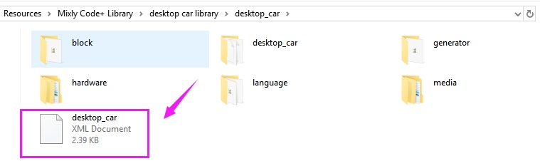
Then import this document into Mixly library. Import custom library successfully!
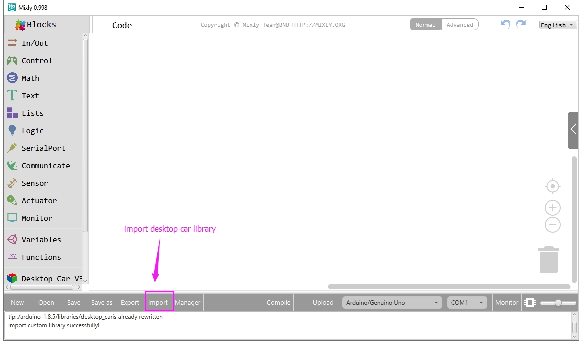
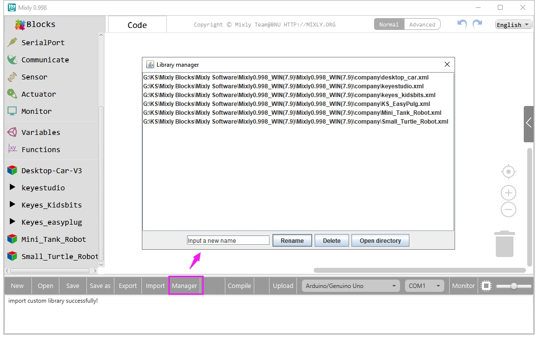
You are able to click “Manager” to manage all imported libraries. Note: sometimes it may exists a conflict between libraries, so should keep only correct car library when using and delete other library.
Basic Projects
Project 1: UNO R3 Built-in LED
Introduction
The UNO R3 development board is the most popular one in Arduino board series. In addition, it is also the best choice for beginners to learn to build electronic circuits and write the source code.
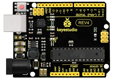
If this is your first experience tinkering with the platform, the UNO R3 is the most robust board you can start playing with.
Let's take a look at the details of this development board with the following chart:
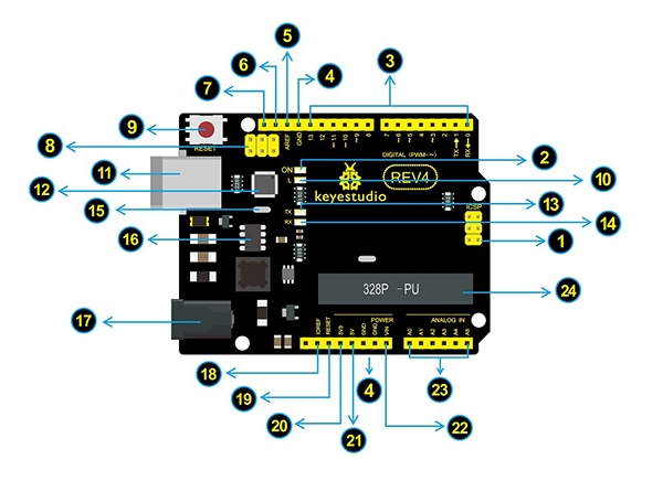
![]()
ICSP (In-Circuit Serial Programming) Header
In most case, ICSP is the AVR, an Arduino micro-program header consisting of MOSI, MISO, SCK, RESET, VCC, and GND. It is often called the SPI (serial peripheral interface) and can be considered an "extension" of the output. In fact, slave the output devices under the SPI bus host. When connecting to PC, program the firmware to ATMEGA328P-PU.
![]()
Power LED Indicator
Powering the Arduino, LED on means that your circuit board is correctly powered on. If LED is off, connection is wrong.
![]()
Digital I/O
OpenELAB UNO R3 (Black) Main Control Board has 14 digital input/output pins (of which 6 can be used as PWM outputs). These pins can be configured as digital input pin to read the logic value (0 or 1). Or used as digital output pin to drive different modules like LED, relay, etc. The pin labeled “〜” can be used to generate PWM.
![]()
GND ( Ground pin headers)
Used for circuit ground

AREF
Reference voltage (0-5V) for analog inputs. Used with analogReference()
![]()
SDA I
IC communication pin

SCL
IIC communication pin
![]()
ICSP (In-Circuit Serial Programming) Header
In most case, ICSP is the AVR Arduino micro-program header consisting of MOSI, MISO, SCK, RESET, VCC, and GND. Connected to ATMEGA 16U2-MU. When connecting to PC, program the firmware to ATMEGA 16U2-MU.

RESET Button
You can reset your OpenELAB UNO R3 (Black) Main Control Board, for example, start the program from the initial status. You can use the RESET button.
![]()
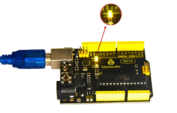
D13 LED
There is a built-in LED driven by digital pin 13. When the pin is HIGH value, the LED is on, when the pin is LOW, it's off.
![]()
USB Connection
OpenELAB UNO R3 (Black) Main Control Board can be powered via USB connector. All you needed to do is connecting the USB port to PC using a USB cable.
![]()
ATMEGA 16U2-MU
USB to serial chip, can convert the USB signal into serial port signal.
![]()
TX LED
Onboard you can find the label: TX (transmit) When OpenELAB UNO R3 (Black) Main Control Board communicates via serial port, send the message, TX led flashes.
![]()
RX LED
Onboard you can find the label: RX(receive ) When OpenELAB UNO R3 (Black) Main Control Board communicates via serial port, receive the message, RX led flashes.
![]()
Crystal Oscillator
How does Arduino calculate time? by using a crystal oscillator. The number printed on the top of the Arduino crystal is 16.000H9H. It tells us that the frequency is 16,000,000 Hertz or 16MHz.
![]()
Voltage Regulator
Convert an external input DC7-12V voltage into DC 5V, then switch DC 5V to the processor and other components. Output DC 5V, the drive current is 2A.

DC Power Jack
OpenELAB UNO R3 (Black) Main Control Board can be supplied with an external power DC7-12V from the DC power jack.
![]()
IOREF
Used to configure the operating voltage of microcontrollers. Use it less.

RESET Header
Connect an external button to reset the board. The function is the same as reset button (labeled 9)
![]()
Power Pin 3V3
A 3.3 volt supply generated by the on-board regulator. Maximum current draw is 50 mA.
![]()
Power Pin 5V
Provides 5V output voltage
![]()
Vin
You can supply an external power input DC7-12V through this pin to OpenELAB UNO R3 (Black) Main Control Board.

Analog Pins
OpenELAB UNO R3 (Black) Main Control Board has 6 analog inputs, labeled A0 through A5. These pins can read the signal from analog sensors (such as humidity sensor or temperature sensor), and convert it into the digital value that can read by microcontrollers) It can also used as digital pins, A0=D14, A1=D15, A2=D16, A3=D17, A4=D18, A5=D19.
![]()
Microcontroller
Each OpenELAB REV4 (Black) Main Control Board has its own microcontroller. You can regard it as the brain of your board. The main IC (integrated circuit) on the Arduino is slightly different from the panel pair. Microcontrollers are usually from ATMEL. Before you load a new program on the Arduino IDE, you must know what IC is on your board. This information can be checked at the top of IC.
Let’s make a simple test for the UNO R3 built-in LED (D13).
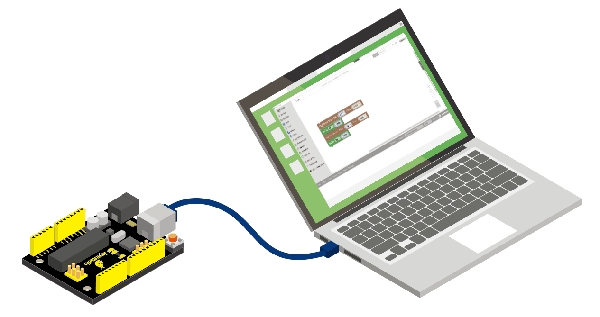
It’s pretty simple to turn a built-in led on and off. We only require UNO R3 control board and a USB cable to enter the wonderful programming world.
Connect your UNO R3 board to the computer’s USB port using a USB cable for communication.
Test Code
Open Mixly blocks platform to get started with coding.
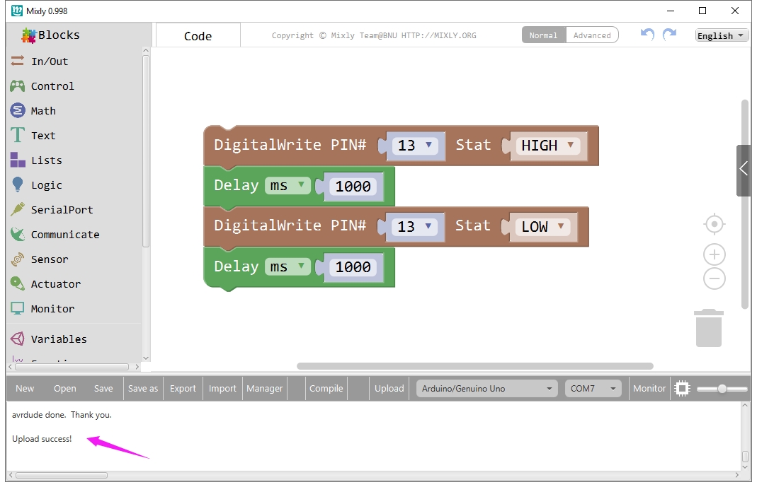
First, click IN/OUT, drag the “DigitalWrite PIN# (0)Stat(HIGH)” block.

This block is used to set the level HIGH or LOW of Digital pin.
Select HIGH is to set the HIGH level.
Select LOW is to set the LOW level.
The HIGH level is the state of high voltage, generally recorded as 1.
High voltage, high current, the LED lights. The LOW level is the state of low voltage, generally recorded as 0. Low voltage, low current, the LED Not lights.
To observe the LED blink obviously, we need to add a Delay block.
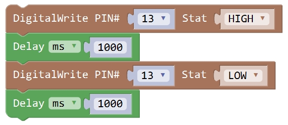
Check the test code below and upload it to your UNO R3 board.
Result
Drag the test code to Mixly window; remember to select the proper board and COM port. Then compile and upload the code to your control board. Upload success message will appear on the bottom bar.
The UNO R3 built-in LED (label “L”) will turn on for 1 second, and then turn off for 1 second, alternately and circularly.
Last updated
Was this helpful?