OpenELAB 4WD Mechanical Arm Robot Smart Car for Arduino
Product Link
Description
As science and technology develops by leaps and bounces, human society moves towards an era of intelligence and automation as well.
Our hands are weak and unresistant to ultra-cold and high temperature environment. In this regard, mechanical arms can totally supplant our hands and work for people.
At present, KEYES group has designed this kind of smart mechanical arm car to tackle the shortcomings of most robot arms, clumsy and fixed. This mechanical smart car reacts and performs its functions by following commands sent by the cellphone connected.
Features
Multi-purpose Function: Anti-fall, obstacle avoidance, following, IR remote control, line tracking, automatically convey and so on.
Easy to Build: soldering circuit is not required.
High Tenacity: high performance car baseplate and metal mechanical arm
High Extension: expand other sensors and modules through motor driver shield.
Multiple Controls: IR remote control, fully automatic and App control(iOS and Android system)
Basic Programming:C language code learning.
Specification
Working voltage: 5v
Input voltage: 7-12V
Maximum output current: 3A
Maximum power dissipation: 25W (T=75℃)
Motor speed: 5V 63 rpm / min
Motor drive form: TB6612 drive
Ultrasonic sensing angle: <15 degrees
Ultrasonic detection distance: 2cm-400cm
Bluetooth remote control distance: 20-50 meters (measured)
Bluetooth APP control: support Android and iOS system
Kit list
1
Car Wheels 68*26mm
4

2
4.5V 200rpm Motor
4

3
PCB Baseplate for 4WD Smart Car V2.0
1

4
4WD Top Board
1

5
Fixing Parts
4
![]()
6
Quick Connectors Line Tracking Sensor
1

7
Quick Connectors Ultrasonic Sensor
1

8
V4.0 Development Board (Compatible Arduino Uno)
1

9
TB6612 Motor Driver Shield
1

10
HM-10 Bluetooth-4.0 V3 Module
1
![]()
11
Quick Connectors IR Receiver
1

12
M2+M3 Wrench
1

13
IR Remote Control
1

14
18650 Battery Holder
1

15
6-Slot AA Battery Holder
1

16
AXK Plain Bearing
1

17
Bearing Cap (attached a yellow protective film)
1

18
19Pcs Acrylic Robot Arm Parts T=3mm
1

19
73*44MM Black Acrylic Board
1

20
Dual-head JST-PH2.0MM-5P 24AWG Dupont Wire 15CM Lead
1

21
MG90S 14G Servo
3

22
Dual-head JST-PH2.0MM-3P 24AWG 8CM Dupont Wire
1

23
2.0*40MM Purple and Black Screwdriver
1

24
8MM Winding Pipe
1

25
USB Cable AM/BM OD:5.0 L=50cm
1

26
M3 Nickel Plated Nuts
21

27
M3*30MM Round Head Screws
8

28
M3*6MM Round Head Screws
38

29
Dual-pass M3*40MM Hex Copper Bush
6

30
M3*8MM Round Head Screws
6

31
Dual-pass M3*10MM Hex Copper Bush
4
![]()
32
M3*10MM Flat Screws
4
![]()
33
M1.4X6 Self-tapping Round Head Screws
6
![]()
34
M2*10MM Round Head Screws
8
35
M2 Nickel Plated Nuts
6

36
M3*10MM Round Head Screws
8

37
M3*12MM Round Head Screws
6

38
M3*16MM Round Head Screws
2

39
M3 Nickel Plated Self-locking Nuts
14
![]()
40
Dual-pass M3*15MM Hex Copper Bush
2

41
M2*5MM Self-tapping Round Head Screws
4
![]()
42
M1.2*5MM Self-tapping Round Head Screws
4
![]()
43
20cm 3pin F-F Dupont Wire
2

44
Red LED Module
1

45
PH2.0mm-4P 24AWG 200MM Dupont Wire Eco-friendly
1

46
3*40MM Red and Black Screwdriver
1

47
Black Ties 3*100MM
6
48
Insulation Gasket
4

49
M2.5*12MM Round Head Screws
6

50
M2.5 Nickel Plated Nuts
6
![]()
Getting Started with Arduino
OpenELAB V4.0 Development Board
You need to know that OpenELAB V4.0 development board is the core of this smart car.
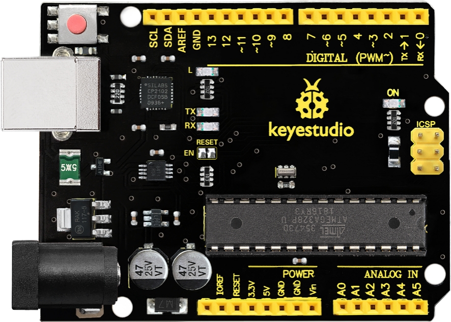
OpenELAB V4.0 development board is an Arduino uno -compatible board, which is based on ATmega328P MCU, and with a cp2102 Chip as a UART-to-USB converter.
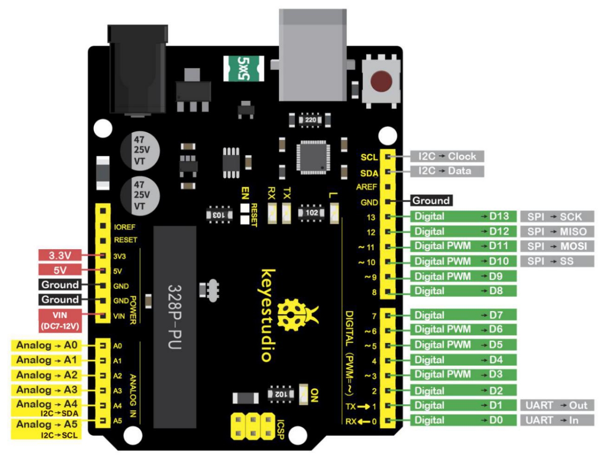
It has 14 digital input/output pins (of which 6 can be used as PWM outputs), 6 analog inputs, a 16 MHz quartz crystal, a USB connection, a power jack, 2 ICSP headers and a reset button.
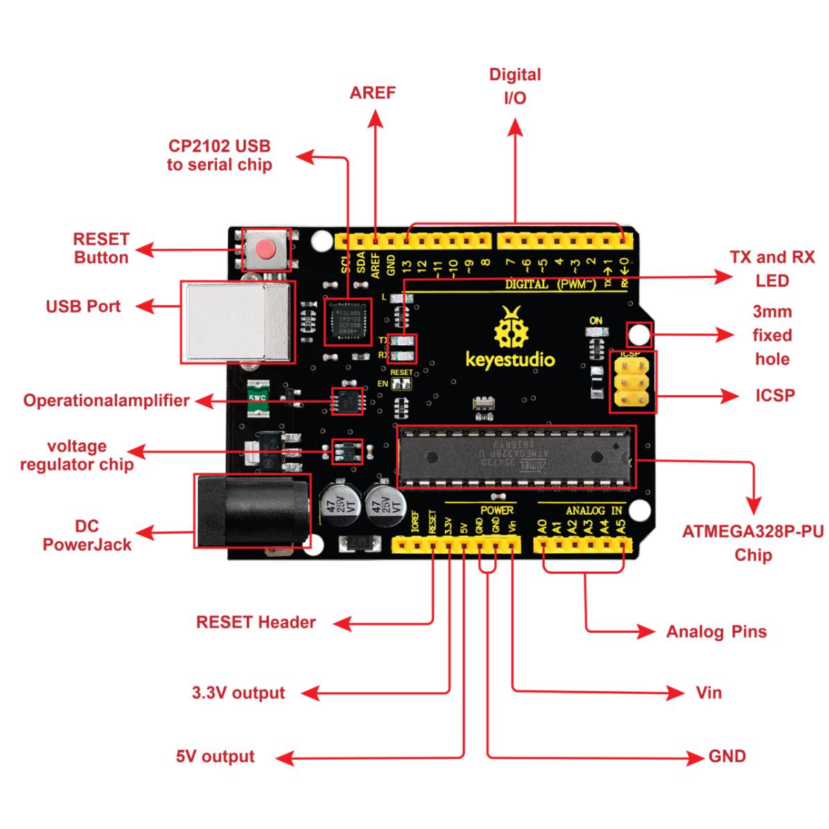
It contains everything needed to support the microcontroller. Simply connect it to a computer with a USB cable or power it via an external DC power jack (DC 7-12V) or via female headers Vin/ GND(DC 7-12V) to get started.
Operating Voltage
5V
Input Voltage (recommended)
DC7-12V
Digital I/O Pins
14 (D0-D13) (of which 6 provide PWM output)
PWM Digital I/O Pins
6 (D3, D5, D6, D9, D10, D11)
Analog Input Pins
6 (A0-A5)
DC Current per I/O Pin
20 mA
DC Current for 3.3V Pin
50 mA
Flash Memory
32 KB (ATmega328P-PU) of which 0.5 KB used by bootloader
SRAM
2 KB (ATmega328P-PU)
EEPROM
1 KB (ATmega328P-PU)
Clock Speed
16 MHz
LED_BUILTIN
D13
Installing Arduino IDE
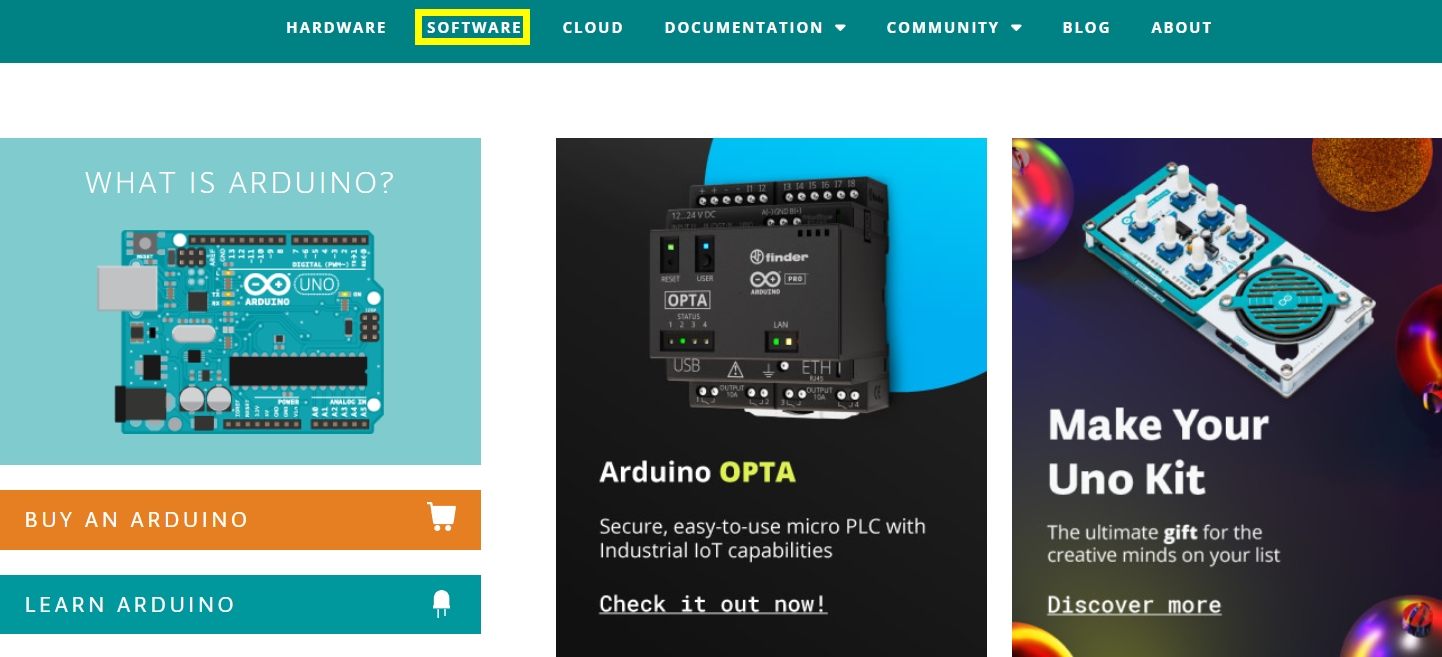
Click the link to start learning how to download software, install drivers, upload code, and install library files.
https://getting-started-with-arduino.readthedocs.io
Install Robot Arm Smart Car
Note: Peel the plastic film off the board first when installing the smart car.
Assemble Body


This is servo 3


Connect Ultrasonic Sensor

Wire up Line Tracking Sensor

Connect Servo

Wire up IR Receiver

Install Front Motors

Install Rear Motors

Mount Battery Holder


Assemble Robot Arms
The following code is used to initialize the angle value of servo. Copy the code in the Arduino IDE and plug in power, then three servos will rotate to an initial angle.
Wiring Diagram
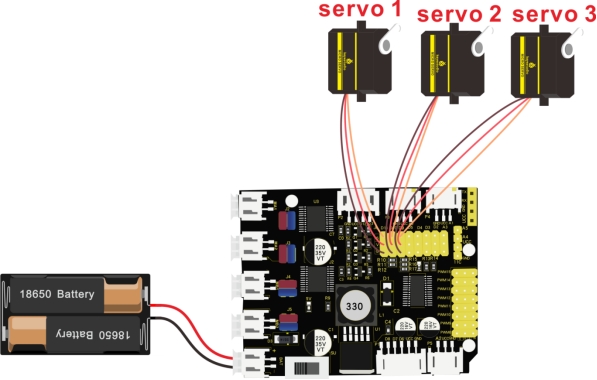
Note: servo 3 sits on the base
Test Code
Installation


Installed on servo 3


Mount with servo 2


Don’t tighten nuts
 The angle between arm and car: 90°


Don’t tighten nuts


This is servo 1


Don’t tighten nuts


Projects
Project 1: LED Light
1. Description:

For starters and enthusiasts, LED Blink is a fundamental program. LED, the abbreviation of light emitting diodes, consists of Ga, As, P, N chemical compounds and so on. The LED can flash in diverse color by altering the delay time in the test code. When in control, power on GND and VCC, the LED will be on if S end is in high level; nevertheless, it will go off.
2. Specification:

Control interface: digital port
Working voltage: DC 3.3-5V
Pin spacing: 2.54mm
LED display color: red
3. What You Need:

4. Wiring Diagram:

The pin -, + and S of LED module are connected to G, V and D3 of shield.
5. Test Code:
6. Test Result:
Upload the program, LED flashes with an interval of 1s.
7. Code Explanation:
pinMode(ledPin,OUTPUT) - This function denotes that the pin is INPUT or OUTPUT.
digitalWrite(ledPin,HIGH) - When pin is OUTPUT, we can set it to HIGH(output 5V) or LOW(output 0V)
8. Extension Practice:
We succeed in blinking the LED. Next, let’s observe what LED will change if we modify the delaying time.
The test result shows that the LED flashes faster. Therefore, we can draw a conclusion that pins and time delaying affect flash frequency.
Last updated
Was this helpful?