OpenELAB EASY PLUG Sensor Learning Kit for Arduino
Product Link
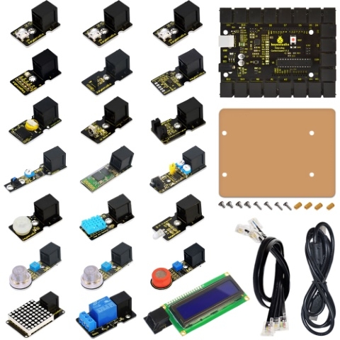
KS0157 OpenELAB EASY plug learning kit for Arduino super makers
● EASY plug starter kit for Arduino
● Based on open-source hardware
● 19 various sensors in one box
● For you to make interesting projects
1.Summary:
What about you and your kids being makers? What about getting creative and making your ideas come true? Well, let’s get started right away!
EASY plug learning kit is developed not only for professional electronic enthusiasts, but also for friends in other lines of work. Even if you have no electronics related knowledge, you can use it to realize your ideas as long as you want to.
The tutorial of this kit has fully considered the learning interest of beginners. Starting from the basics to more complex lessons, well-arranged content and a connection diagram for every lesson help you get started easily and quickly in learning Arduino.
Its unique EASY plug interface makes the wire connection easier than ever! You never have to worry about wrong connection or complicated soldering, avoiding component damage due to wrong wiring or wrong soldering. It’s both safe and environmental-friendly.
2.Kit list
No.
Name
QTY
Picture
1
EASY plug controller Board
1

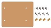
2
Acrylic Board + Copper bush set
1
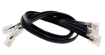
3
EASY plug cable
3
4
USB cable
1

5
EASY plug Piranha LED Module
3

6
EASY plug Line Tracking Sensor
1

7
EASY plug Infrared obstacle avoidance sensor
1

8
EASY plug Photo Interrupter Module
1

9
EASY plug PIR Motion Sensor
1

10
EASY plug DS18B20 Temperature Sensor
1

11
EASY plug IR Receiver Module
1

12
EASY plug IR Transmitter Module
1

13
EASY plug Single Relay Module
1

14
EASY plug ADXL345 Three Axis Acceleration Module
1

15
EASY plug DHT11 Temperature and Humidity Sensor
1

16
EASY plug DS3231 Clock Module
1

17
EASY plug Analog Gas Sensor
1

18
EASY plug Analog Alcohol Sensor
1

19
EASY plug MQ135 Air Quality Sensor
1

20
EASY plug BMP180 Barometric Pressure Sensor
1

21
EASY plug Bluetooth Module
1

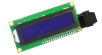
22
EASY plug 1602 I2C Module
1
23
EASY plug I2C 8x8 LED Matrix
1

3.Lesson list
1. Who’s blinking
2. Flowing light
3. My LCD display
4. Running light
5. Control electricity
6. Black or white
7. Is there something upfront
8. Is the light blocked
9. It’s moving
10. Make a clock
11. What’s the air pressure
12. Bluetooth so easy
13. I receive a signal
14. Transmit a signal
15. How’s the air quality
16. Is there a gas leakage
17. Did he drink
18. Somebody is in this area
19. What’s the temperature
20. How humid & hot is the air
4.Lesson details:
Lesson 1: Who’s blinking
Introduction
As the first lesson of this kit, we will begin with something simple. In this lesson, all you need to do is to connect an LED to one of the digital pins of main board. With the program we provided here, you can easily control the blinking of an LED.
Hardware required
EASY plug controller Board *1
EASY plug cable *1
USB cable *1
EASY plug Piranha LED Module *1
First, let’s take a look at this Piranha LED Module.
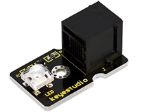
This is a special LED module. When you connect it to ARDUINO, after program, it can emit beautiful light. Of course, you can also control it using PWM. It will be like fireflies at night. Isn’t it cool? We can also combine it with other sensors to do various interesting interactive experiments. Below are its specifications:
Module type: digital
Working voltage: 5V
Distance between pins: 2.54mm
Size: 33.7*20mm
Weight: 3g
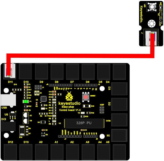
Connection Diagram
Now, let’s connect this module to the D11 port of the controller board using the EASY plug cable, just as simple as that!
Sample Code
Connect the board to your PC using the USB cable; copy below code into Arduino IDE, and click upload to upload it to your board.
Result
The LED will be on for one second, and then off for one second with an interval of one second, just like a shining eye blinking.
Lesson 2: Flowing light
Introduction
LED can do many things. I believe you have seen billboards with lights changing to form various patterns. Now, you can make one! This lesson is called Flowing light. We will need 2 more EASY plug cables and 2 more LEDs than the previous lesson.
Hardware required
EASY plug controller Board *1
EASY plug cable *3
USB cable *1
EASY plug Piranha LED Module *3
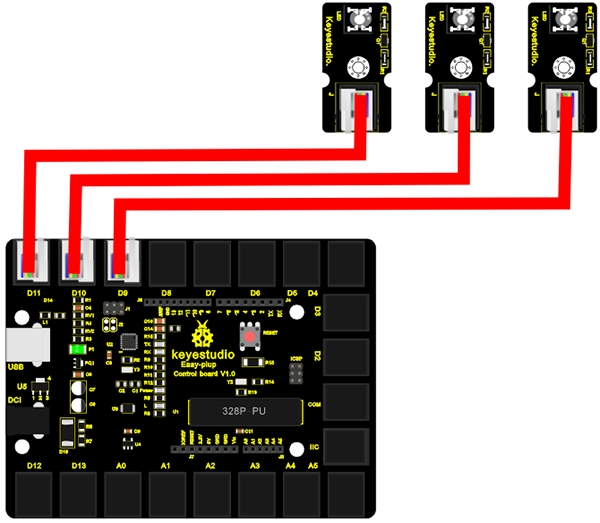
Connection Diagram
Now, connect the LED modules one by one to D9, D10 and D11 ports of the controller board using the EASY plug cables.
Sample Code
Connect the board to your PC using the USB cable; copy below code into Arduino IDE, and click upload to upload it to your board.
Result
3 LEDs turn on one by one, and then turn off one by one, just like flowing light.
Lesson 3: My LCD display
LCDs are very common and useful in our life. It’s widely applied on phone screens and TV screens. In this lesson, we will introduce you a 1602 LCD module to help you understand how it works.
Hardware required
EASY plug controller Board x1
USB cable x1
EASY plug cable x1
EASY plug 1602 I2C Module x1
First, let’s take a look at this 1602 I2C Module.
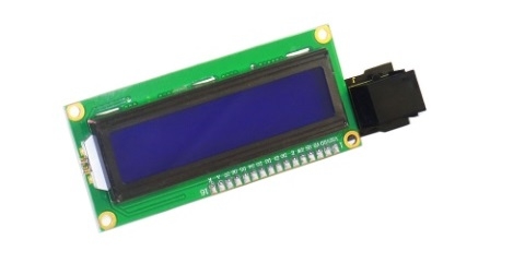
EASY plug 1602 I2C module is a 16 character by 2 line LCD display with blue background and white backlight. This LCD is ready-to-use because it is compatible with the Arduino Liquid Crystal Library. The original 1602 LCD needs 7 IO ports to be up and running, this easy plug design makes the wire connection easier than ever. Below are its specifications:
I2C Address: 0x27
Back lit (Blue with white char color)
Supply voltage: 5V
Adjustable contrast
Size: 98*36mm
Weight: 4g
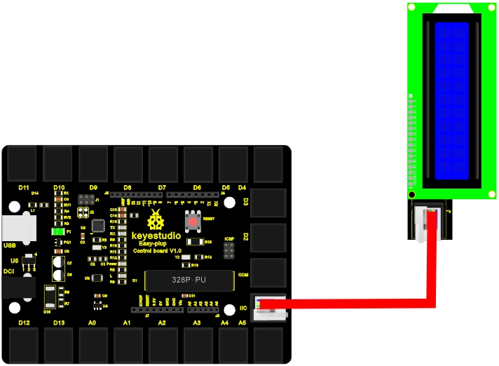
Connection Diagram
Now, connect the LCD module to the IIC port of the controller board using the EASY plug cable.
Sample Code
Connect the board to your PC using the USB cable; copy below code into Arduino IDE, and click upload to upload it to your board.
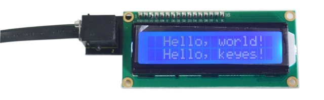
Result
After power is on, the first line of LCD will display “Hello, world!”, and the second line will display “Hello, keyes!”.
Lesson 4: Running light
Walking down a business street a night, you must be amazed by all the beautiful lights around you. In this lesson, we will make one of our own and learn how those beautiful lights are achieved.
Hardware required
EASY plug controller Board x1
USB cable x1
EASY plug cable x1
EASY plug I2C 8x8 LED Matrix x1
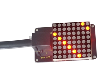
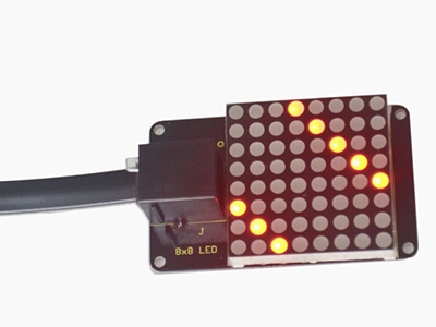
Let’s first meet this EASY plug I2C 8x8 LED Matrix.
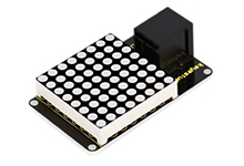
What’s better than a single LED? Lots of LEDs! A fun way to make a small display is to use an 8x8 matrix. This matrix uses a driver chip that does all the heavy lifting for you: They have a built in clock so they multiplex the display. They use constant-current drivers for ultra-bright, consistent color, 1/16 step display dimming, all via a simple I2C interface. Below are its specifications:
Supply voltage: 4.5V-5.5V
Maximum display: 16*8
Size: 53*32mm
Weight: 4g
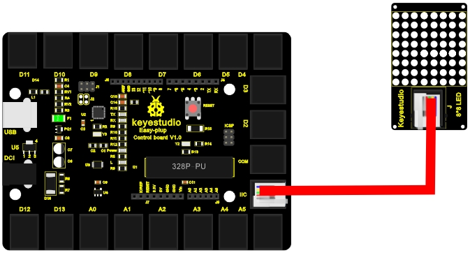
Connection Diagram
Now, connect the module to the IIC port of the controller board using the EASY plug cable.
Sample Code
Connect the board to your PC using the USB cable; copy below code into Arduino IDE, and click upload to upload it to your board.
Result
After all the above are done (circuit connection, program uploading), press the “reset” button on the main board. The LED matrix begins to display a beautiful light pattern, as pictures show below.
Lesson 5: Control electricity
In this lesson, we will learn to use a very important element in the switch family. It’s called relay. Relay is specially used in controlling a high-power circuit by a low-power signal. Here, we will only do a simple module test due to limited resources while you can expend the circuit and the program to have more fun with it.
Hardware required
EASY plug controller Board x1
USB cable x1
EASY plug cable x1
EASY plug Single Relay Module x1
Next is a brief introduction of this relay module.
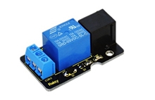
Relay is an automatic switch element with isolation function. It’s widely used in remote control, remote sensing, communication, automatic control, mechatronics and electronic devices. It is one of the most important control elements. Besides, it’s easy to control and use just by inputting different level signals to corresponding ports of the relay. The single relay we introduced here has a status indicator light, convenient for you to observe the on and off status of the relay. Below are its specifications:
Type: Digital
Rated current: 10A (NO) 5A (NC)
Maximum switching voltage: 150VAC 24VDC
Digital interface
Control signal: TTL level
Rated load: 8A 150VAC (NO) 10A 24VDC (NO), 5A 250VAC (NO/NC) 5A 24VDC (NO/NC)
Maximum switching power: AC1200VA DC240W (NO) AC625VA DC120W (NC)
Contact action time: 10ms
Size: 46.5*28mm
Weight: 15g
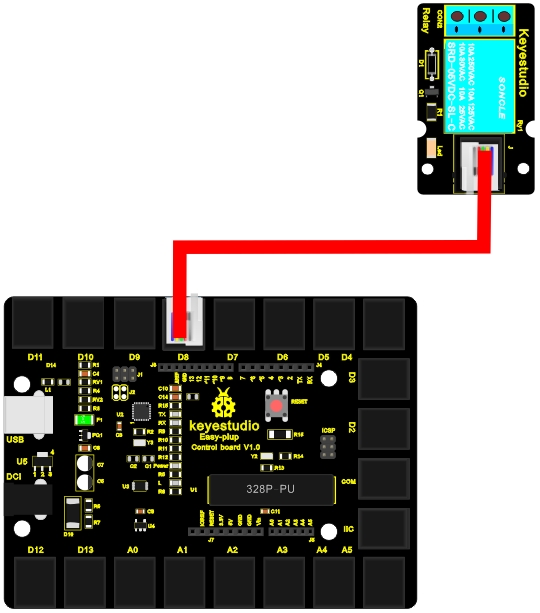
Connection Diagram
Now, let’s connect this module to the D8 port of the controller board using the EASY plug cable.
Sample Code
Connect the board to your PC using the USB cable; copy below code into Arduino IDE, and click upload to upload it to your board.
Result
After all the above are done, you can hear the relay module is ticking, and the LED on the module is being on for 1S (“ON” contacts are connected), and off for 1S (“ON” contacts are connected).
Lesson 6: Black or white
Have you seen a line tracking smart car? That is a car going along a line with specific color. In this lesson, we will learn how to achieve such result. Here, we will use a Line Tracking Sensor and a Piranha LED Module to help you better understand how it works.
Hardware required
EASY plug controller Board x1
USB cable x1
EASY plug cable x2
EASY plug Piranha LED Module x1
EASY plug Line Tracking Sensor x1
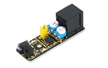
First, we will learn something about this Line Tracking Sensor.
This Line Tracking Sensor can detect white line in black and black line in white. The single line-tracking signal provides a stable output signal TTL for a more accurate and more stable line. Multi-channel option can be easily achieved by installing required number of line-tracking sensors.
The working principle is simple, using infrared light’s different reflectivity of different color, and converting the strength of the reflected signal into current signal.
Below are its specifications:
Power supply: +5V
Operating current: < 10mA
Operating temperature range: 0°C ~ + 50°C
Output interface: 3-wire interface (1 - signal, 2 - power, 3 - power supply negative)
Output Level: TTL level
Size: 56.8*16mm
Weight: 3g
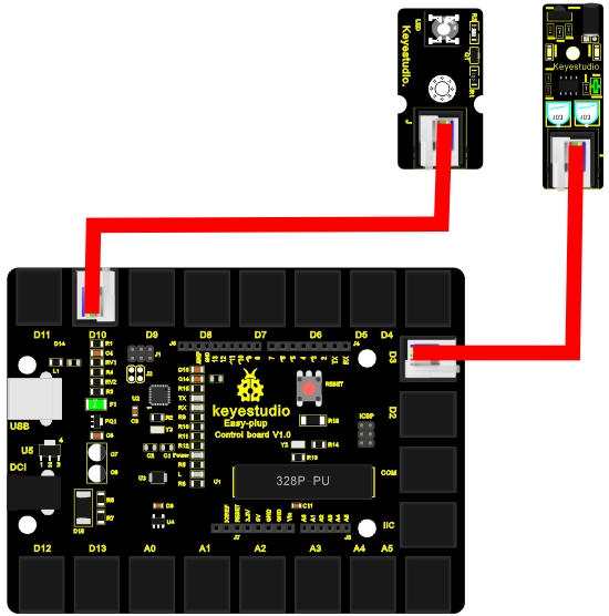
Connection Diagram
Now, connect the LED module to the D10 port of the controller board, and line tracking sensor module to D3 port using the EASY plug cables.
Sample Code
Connect the board to your PC using the USB cable; copy below code into Arduino IDE, and click upload to upload it to your board.
Result
After power is on, open serial monitor, you can see the current value is 1, the LED on the module remains off and the Piranha LED is on. When you place a white card in front of the sensor, you can see the LED on the module turns on, the value changes to 0 and the Piranha LED turns off. Now, place a black card in front of the sensor, you can see the result is the same with when there is nothing in front of the sensor. This principle is applied to line tracking smart car by programming the result.
Lesson 7: Is there something upfront
If you are interested in smart cars, you might be intrigued in how they avoid obstacles. It’s not like the smart cars have eyes, right? In this lesson, we will learn how to use a infrared obstacle avoidance sensor. This sensor is widely applied in obstacle avoidance, fall prevention of smart cars, product counting etc. After this lesson, you will know how obstacle avoidance function of smart cars can be achieved.
Hardware required
EASY plug controller Board x1
USB cable x1
EASY plug cable x2
EASY plug Piranha LED Module x1
EASY plug Infrared obstacle avoidance sensor x1
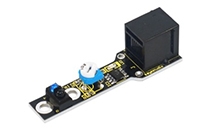
Below is a brief introduction of this infrared obstacle avoidance sensor.
Infrared obstacle avoidance sensor is equipped with distance adjustment function and is especially designed for wheeled robots. This sensor has strong adaptability to ambient light and is of high precision. It has a pair of infrared transmitting and receiving tube. When infrared ray launched by the transmitting tube encounters an obstacle (its reflector), the infrared ray is reflected to the receiving tube, and the indicator will light up. A robot mounted with the sensor can sense changes in the environment. Below are its specifications:
Working voltage: DC 3.3V-5V
Working current: ≥20mA
Working temperature: -10℃—+50℃
Detection distance: 2-1000px
IO Interface: 4 wire interface (-/+/S/EN)
Output signal: TTL voltage
Accommodation mode: Multi-circle resistance regulation
Effective Angle: 35°
Size: 51*16.5mm
Weight: 5g
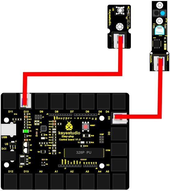
Connection Diagram
Now, connect the LED module to the D10 port of the controller board and obstacle avoidance sensor to D3 port using the EASY plug cables.
Sample Code
Connect the board to your PC using the USB cable; copy below code into Arduino IDE, and click upload to upload it to your board.
Result
When power is on, use a screw driver to adjust the two knobs on the module. P LED is always on and S LED is out. At this time, the piranha LED is on. Now, put your hand in front of the sensor, you can see the S LED front of the sensor turns on and the piranha LED is out. If you open the serial monitor, you can see when it detects an object, the output is “0”; no object, output is “1”. These different outputs can be used as a switch signal to control smart car actions and that’s how smart cars realize obstacle avoidance function.
Lesson 8: Is the light blocked
If you have seen a production line, you must be wondering how the machines do the workpiece counting. Well, in this lesson, we will show you how this technology is achieved.
Hardware required
EASY plug controller Board x1
USB cable x1
EASY plug cable x2
EASY plug Piranha LED Module x1
EASY plug Photo Interrupter Module x1
In realizing the counting process, below is a critical part called Photo Interrupter Module.
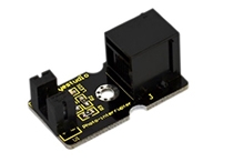
Upright part of this sensor is an infrared emitter and on the other side, it’s a shielded infrared detector. By emitting a beam of infrared light from one end to another end, the sensor can detect an object when it passes through the beam. It is used for many applications including optical limit switches, pellet dispensing, general object detection, etc. Below are its specifications:
Supply Voltage: 3.3V to 5V
Interface: Digital
Size: 38x20mm
Weight: *g
Connection Diagram
Now, connect the LED module to the D10 port of the controller board and Photo Interrupter Module to D3 port using the EASY plug cables.
Sample Code
Connect the board to your PC using the USB cable; copy below code into Arduino IDE, and click upload to upload it to your board.
Result
After the above are done, the LED on the module will be on and the piranha LED will be off; place a paper card between the two ends of the module, you can see the LED on the module is off, and the piranha will be on. Now, you have a clear idea of how piece counting is done.
Lesson 9: It’s moving
In this lesson, we will learn how to measure the static acceleration of an object in its X, Y and Z direction using an ADXL345 three axis acceleration module. This module is also suitable for measuring dynamic acceleration.
Hardware required
EASY plug controller Board x1
USB cable x1
EASY plug cable x1
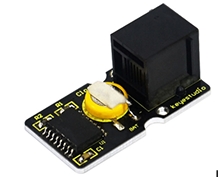
EASY plug ADXL345 Three Axis Acceleration Module x1
Below is a brief introduction of this module.
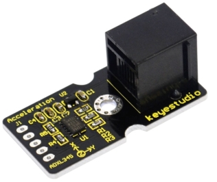
The ADXL345 module is a 3-axis MEMS accelerometer with low power consumption and compact design. It’s of high resolution of 13-bit, measurement up to ±16g(gravitational force). Digital output data is formatted as 16-bit twos complement and is accessible through either a SPI (3- or 4-wire) or I2C digital interface. Below are its specifications:
2.0-3.6VDC Supply Voltage
Ultra Low Power: 40uA in measurement mode, 0.1uA in standby@ 2.5V
Tap/Double Tap Detection
Free-Fall Detection
SPI and I2C interfaces
Size: 40*20mm
Weight: 3g
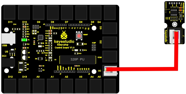
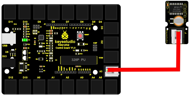
Connection Diagram
Now, let’s connect this module to the IIC port of the controller board using the EASY plug cable.
Sample Code
Connect the board to your PC using the USB cable; copy below code into Arduino IDE, and click upload to upload it to your board.
Result
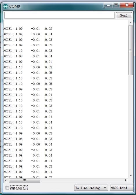
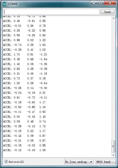
Now, open serial monitor, you can see it displays data as pic 1; when you move the module towards different direction, you can see the data changes as pic 2.
Pic 1:
Pic 2:
Lesson 10: Make a clock
Time is of essence in our life. We have all sort of stuff that tells time. In this lesson, we will make a device of our own using the DS3231 clock module. Combine with a buzzer, you can make an alarm or just a time telling device when combined with an LCD.
Hardware required
EASY plug controller Board x1
USB cable x1
EASY plug cable x1
EASY plug DS3231 Clock Module x1
The DS3231 is a low-cost, extremely accurate I2C real-time clock (RTC) with an integrated temperature-compensated crystal oscillator (TCXO) and crystal. The device incorporates a battery input, and maintains accurate timekeeping when main power to the device is interrupted. The integration of the crystal resonator enhances the long-term accuracy of the device as well as reduces the piece-part count in a manufacturing line. The DS3231 is available in commercial and industrial temperature ranges, and is offered in a 16-pin, 300-mil SO package. Below are its specifications:
Temperature range: -40 to +85; Timing accuracy : ± 5ppm (±0.432 seconds / day)
Device package and function compatible with DS3231
Two calendar clock
Output: 1Hz and 32.768kHz
Reset output and Input Debounce of Pushbutton
High speed (400kHz), I2C serial bus
Supply voltage: +3.3V to +5.5V
Digital temperature sensor with a precision of±3℃
Working temperature: -40 ~ ℃ to +85 ~ ℃
16 pins Small Outline Package (300mil)
Certified by American Association of Underwriters Laboratories (UL)
Size: 38*20mm
Weight: 4g
Connection Diagram
Now, connect the DS3231 module to the IIC port of the controller board using the EASY plug cable.
Sample Code
Connect the board to your PC using the USB cable; copy below code into Arduino IDE, and click upload to upload it to your board.
Result
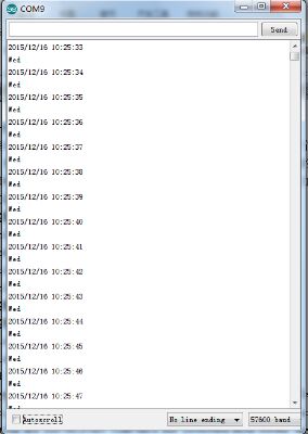
Now, open serial monitor, set baud rate to 57600, it will display the date we set in the program. You can change the code for it to display different dates; the module will then begin time counting, as below picture shows.
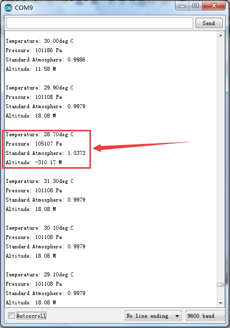
Lesson 11: What’s the air pressure
In this lesson, we will measure the Temperature, Pressure, Standard Atmosphere and Altitude using a BMP180 Barometric Pressure Sensor. You can also apply the experiment principle to make a vertical velocity indicator, a device that can regulate fan power etc.
Hardware required
EASY plug controller Board x1
USB cable x1
EASY plug cable x1
EASY plug BMP180 Barometric Pressure Sensor x1
We will briefly take a look at this BMP180 first.
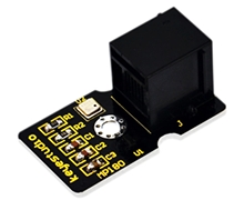
BMP180 is a pressure sensor with high precision, compact design and low power consumption. It can be used in mobile devices. Minimum absolute accuracy reaches 0.03hpa with only 3uA power consumption. Below are its specifications:
Pressure range: 300~1100hPa (Altitude 9000M~-500M)
Supply voltage: 1.8V~3.6V (VDDA), 1.62V~3.6V(VDDD)
Low power consumption: 0.5uA, standard mode
I2C interface
With temperature output
Leadless, comply with RoHS
MSL 1 response time: 7.5ms
Standby current: 0.1uA
No need for external clock circuit
Size: 35*20mm
Weight: 6g
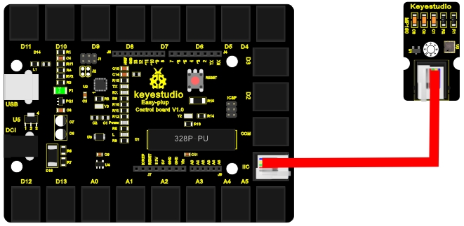
Connection Diagram
Now, connect the BMP180 module to the IIC port of the controller board using the EASY plug cable.
Sample Code
Connect the board to your PC using the USB cable; copy below code into Arduino IDE, and click upload to upload it to your board.
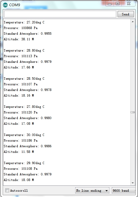
Result
Now, open serial monitor, set baud rate to “9600”, serial monitor displays content as pic 1; when you blow air into the sensor with your month, you can see the pressure changes as pic 2 shows.
Pic 1:
Pic 2:
Lesson 12: Bluetooth so easy
Wireless communication is very common in our everyday life. In this lesson, we will use a Bluetooth module and the LCD module to help you better understand how this technology works.
Hardware required
EASY plug controller Board x1
USB cable x1
EASY plug cable x2
EASY plug 1602 I2C Module x1
EASY plug Bluetooth Module x1
First, let’s take a look at this EASY plug Bluetooth Module.
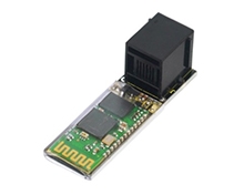
This Bluetooth module can easily achieve serial wireless data transmission. Its operating frequency is among the most popular 2.4GHz ISM frequency band (i.e.Industrial, scientific and medical). It adopts Bluetooth 2.1+EDR standard. In Bluetooth 2.1, signal transmit time of different devices stands at a 0.5 seconds interval so that the workload of bluetooth chip can be reduced substantially and more sleeping time can be saved for bluetooth. Below are its specifications:
Bluetooth protocol: Bluetooth 2.1+ EDR standard
USB protocol: USB v1.1/2.0
Operating frequency: 2.4GHz ISM frequency band
Modulation mode: Gauss frequency Shift Keying
Transmit power: ≤ 4dBm, second stage
Sensitivity: ≤-84dBm at 0.1% Bit Error Rate
Transmission speed: 2.1Mbps(Max)/160 kbps(Asynchronous);
1Mbps/1Mbps(Synchronous)
Safety feature: Authentication and encryption
Supported configuration: Bluetooth serial port (major and minor)
Supply Voltage: +3.3 VDC 50mA
Operating temperature: -20 to 55℃
Size: 49*15.4mm
Weight: 4g
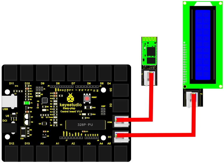
Connection Diagram
Now, connect the Bluetooth module to the COM port of the controller board, and LCD module to IIC port using the EASY plug cables.
Sample Code
Connect the board to your PC using the USB cable; copy below code into Arduino IDE, and click upload to upload it to your board.
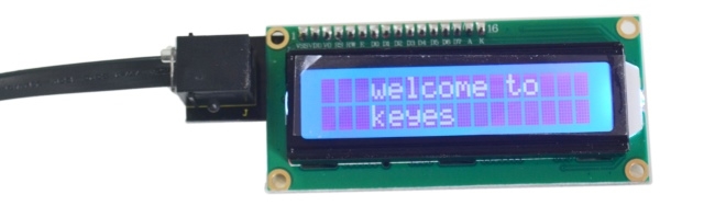
Result
In this experiment, you need to download an App called “BTClient” to your phone. After power is on, the LED on the Bluetooth module begins to blink; open Bluetooth on your phone, pair up the device, enter PIN number “1234”; device is paired. Now, open BTClient, search and pair up the device. The LED on the Bluetooth module stops blinking and becomes stable. Enter “a” on BTClient page, you can see the LCD displays “welcome to keyes” for 1 second. When you input “a” again, the LCD will display the information again.
Lesson 13: I receive a signal
IR is widely used in remote control. In this lesson, we will use a IR receiver module as a decoder of command from any IR remote controller. Thus, you know how IR can realize control of a robot or how IR is applied in interactive works.
Hardware required
EASY plug controller Board x1
USB cable x1
EASY plug cable x2
EASY plug IR Receiver Module x1
EASY plug 1602 I2C Module x1
Mini IR remote controller x1 (not included)
Below is a brief introduction of IR Receiver Module so you can gain a better idea of how IR remote control works.
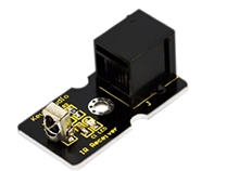
Infrared receiver is a component with functions of reception, amplification, and demodulation. Its internal IC has already completed demodulation so it directly outputs digital signal. This module is usually used together with IR transmitter module. Below are its specifications:
Power Supply: 5V
Interface:Digital
Modulate Frequency: 38Khz
Module interface socket:JST PH2.0
Size: 38*20mm
Weight: 4g
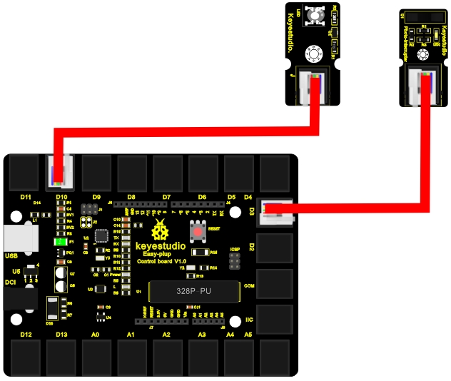
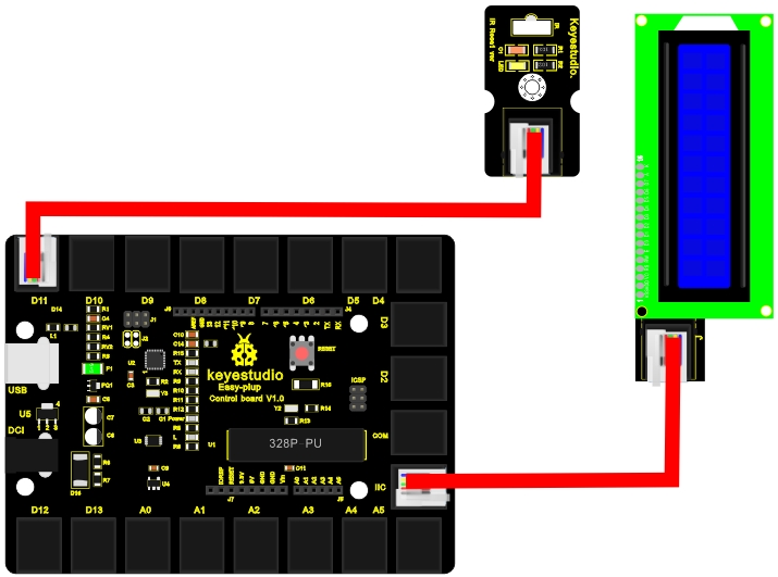
Connection Diagram
Now, connect the IR Receiver Module to the D11 port of the controller board, and LCD module to IIC port using the EASY plug cables.
Sample Code
Connect the board to your PC using the USB cable; copy below code into Arduino IDE, and click upload to upload it to your board.
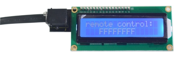
Result
After the above are done, you can see the first line of LCD displays “remote control:”; after you press buttons on the remote controller, in the second line of LCD, you can see it displays a hexadecimal number for 0.5S corresponding to each button; if you hold a button in pressed state, you can see the second line displays “FFFFFFFF”.


Lesson 14: Transmit a signal
In the above lesson, we use a remote controller as an IR transmitting device. Here, we introduce you an IR Transmitter Module. IR Transmitter is a critical part of a remote controller that transmits IR signal. It’s usually used with the receiver module to complete a full transceiving process. Here, due to limited resource of EASY plug main controller board (requires two), we will do a simple IR transmitting test for you to better understand IR communication.
Hardware required
EASY plug controller Board x1
USB cable x1
EASY plug cable x2
EASY plug IR Transmitter Module x1
EASY plug Digital Push Button x1 (not included, refer to EASY plug starter kit)
Below is a brief introduction of IR transmitter module.
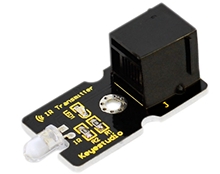
Infrared transmitting tube, also known as infrared emitting diode, belongs to the diode family. It is a light-emitting device that can directly convert electrical energy to near-infrared light and emit. Its structure and principle is similar to an LED. Only material of semiconductor is different. This module is usually used together with IR receiver module. Below are its specifications:
Power Supply: 3-5V
Infrared center frequency: 850nm-940nm
Infrared emission angle: about 20degree
Infrared emission distance: about 1.3m (5V 38Khz)
Interface socket: JST PH2.0
Mounting hole: inner diameter is 3.2mm, spacing is 15mm
Size: 43.8*20mm
Weight: 3g
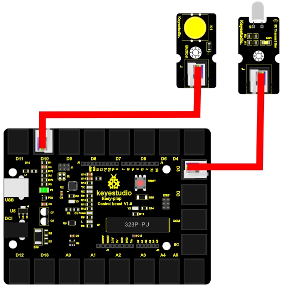
Connection Diagram
Now, connect the button module to the D10 port of the controller board, and IR Transmitter Module to D3 port using the EASY plug cables.
Sample Code
Connect the board to your PC using the USB cable; copy below code into Arduino IDE, and click upload to upload it to your board.
Result
After the above are done, press the button, the LED on the module flashes, and the IR transmitter module will transmit “A90” as programmed in the code. If you have an IR receiving device, you can receive “A90”. Release the button, it will stop the transmitting and the LED on the module will be off.
Lesson 15: How’s the air quality
We always say man cannot live without water and air. So we know how important air is to us. In this lesson, we will introduce you an air quality sensor for you to detect the quality of the air. The experiment principle can be directly applied to factories in detecting harmful gases.
Hardware required
EASY plug controller Board x1
USB cable x1
EASY plug cable x2
Lighter x1 (not included)
EASY plug Piranha LED Module x1
EASY plug MQ135 Air Quality Sensor x1
In this lesson, one critical component is MQ135 Air Quality Sensor. Below is its brief introduction.
MQ135 adopts SnO2 as its gas sensitive material because SnO2 has low electrical conductivity in the clean air. So when surrounded by polluted air, the electrical conductivity of MQ135 will increase with the increase of pollutants, and the change in electrical conductivity can be converted to corresponding output signal.
MQ135 has a high sensitivity to Ammonia, sulfide, benzene vapor, smoke and other harmful gases. It can detect various harmful gases, making it a cost-effective choice suitable for multiple applications. Below are its specifications:
Product model: MQ135
Product type: Semiconductor gas sensor
Target gas: Ammonia; methylbenzene; hydrogen
Standard circuit: Loop voltage Vc ≤24V DC
Heater voltage: VH 5.0V±0.2V AC or DC
Load resistance: Adjustable RL
Size: 56*20mm
Weight: 6g
Connection Diagram
Now, connect the LED module to the D10 port of the controller board, and MQ-135 module to IIC port using the EASY plug cables.
Sample Code
Connect the board to your PC using the USB cable; copy below code into Arduino IDE, and click upload to upload it to your board.
Result
After all the above are done, you can see the power LED1 on the module is on, for LED2 on the module, you need to use a screw driver to adjust the knob for LED2 to be in a “off” state when it’s about to be turned on. Now, the piranha LED is off and open serial monitor, you can see it displays “Gas not leak”; then, turn on the lighter and turn off after a little while, place the lighter mouth into the sensor sensing area, you can see LED2 on the module and piranha LED are both on, and serial monitor displays “Gas leakage”.
Lesson 16: Is there gas leakage
This lesson is very much the same as the above one. The only difference is that we use a different gas sensor. The experiment principle can also be directly applied to factories in detecting harmful gases.
Hardware required
EASY plug controller Board x1
USB cable x1
EASY plug cable x2
Lighter x1 (not included)
EASY plug Piranha LED Module x1
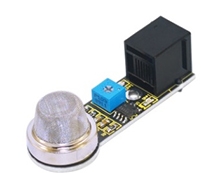
EASY plug Analog Gas Sensor x1
Below is a brief introduction of this analog gas sensor.
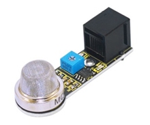
This analog gas sensor - MQ2 is used in gas leakage detecting equipment in consumer electronics and industrial markets. This sensor is suitable for detecting LPG, I-butane, propane, methane, alcohol, Hydrogen and smoke. It has high sensitivity and quick response. In addition, the sensitivity can be adjusted by the potentiometer. Below are its specifications:
Power supply: 5V
Interface type: Analog
Wide detecting scope
Quick response and High sensitivity
Simple drive circuit
Stable and long lifespan
Size: 56*20mm
Weight: 8g
Connection Diagram
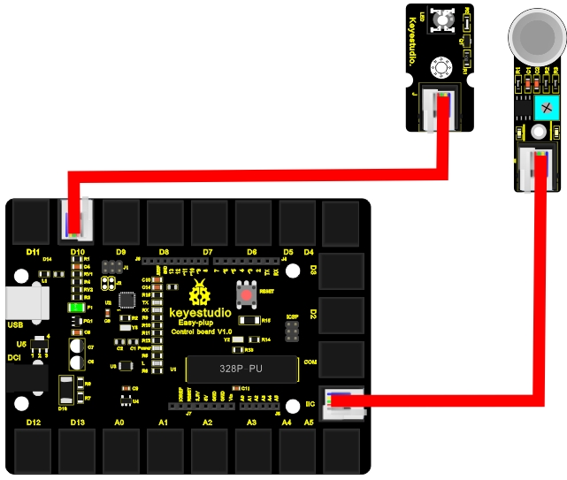
Now, connect the LED module to the D10 port of the controller board, and gas sensor to IIC port using the EASY plug cables.
Sample Code
Connect the board to your PC using the USB cable; copy below code into Arduino IDE, and click upload to upload it to your board.
Result
After all the above are done, you can see the power LED1 on the module is on, for LED2 on the module, you need to use a screw driver to adjust the knob for LED2 to be in a “off” state when it’s about to be turned on. Now, the piranha LED is off and open serial monitor, you can see it displays “Gas not leak”; then, turn on the lighter and turn off after a little while, place the lighter mouth into the sensor sensing area, you can see LED2 on the module and piranha LED are both on, and serial monitor displays “Gas leakage”.
Lesson 17: Did he drink
In previous two lessons, we introduced you two types of gas sensors. Here, we will introduce you another gas sensor especially used for detecting alcohol. Also, instead of an LED to tell whether there is alcohol or not, we will use an LCD.
Hardware required
EASY plug controller Board x1
USB cable x1
Some alcohol (not included)
A piece of cloth (not included)
EASY plug cable x2
EASY plug 1602 I2C Module x1
ASY plug Analog Alcohol Sensor x1
First, let’s learn a little bit about this analog alcohol sensor.
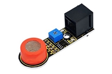
This analog gas sensor - MQ3 is suitable for detecting alcohol. It can be used in a Breath analyzer Also it has high sensitivity to alcohol and low sensitivity to Benzine. The sensitivity can be adjusted by the potentiometer. Below are its specifications:
Power supply: 5V
Interface type: Analog
Quick response and High sensitivity
Simple drive circuit
Stable and long service life
Size: 56*15mm
Weight: 6g
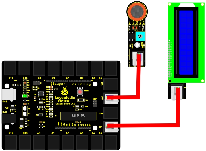
Connection Diagram
Now, connect the alcohol sensor to the D2 port of the controller board, and LCD module to IIC port using the EASY plug cables.
Sample Code
Connect the board to your PC using the USB cable; copy below code into Arduino IDE, and click upload to upload it to your board.
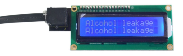
Result
After all the above are done, you can see the power LED1 on the module is on, for LED2 on the module, you need to use a screw driver to adjust the knob for LED2 to be in a “off” state when it’s about to be turned on. Now, the LCD is displaying “Alcohol not leak”; spill some alcohol on the cloth and place it on the sensing area of the sensor, you can see the LCD displays “Alcohol leakage”.

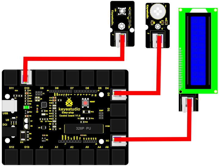
Lesson 18: Somebody is in this area
Introduction
In this lesson, we will combine PIR Motion Sensor, 1602 I2C Module and Piranha LED Module to make a device to detect whether there is someone or some animals around. The principle of this experiment can be applied in automatic switch of corridor light and burglar alarm etc.
Hardware required
EASY plug controller Board *1
USB cable *1
EASY plug cable *3
EASY plug Piranha LED Module *1
EASY plug 1602 I2C Module *1
EASY plug PIR Motion Sensor *1
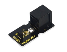
Below is a brief introduction of EASY plug PIR Motion Sensor.
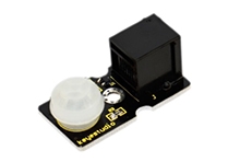
Pyroelectric infrared motion sensor can detect infrared signals from a moving person or moving animal, and outputs switching signals. It has advantages of low power consumption, good concealing, low cost etc. It can be applied to a variety of occasions to detect the movement of human body. Below are its specifications:
Input Voltage: 3.3 ~ 5V, 6V Maximum
Working Current: 15uA
Working Temperature: -20 ~ 85 ℃
Output Voltage: High 3V, low 0V
Output Delay Time (High Level): About 2.3 to 3 Seconds
Detection angle: 100 °
Detection distance: 7 meters
Output Indicator LED (When output HIGH, it will be ON)
Pin limit current: 100mA
Size: 36.4*20mm
Weight: 4g
Connection Diagram
Now, connect the LED module to the D10 port of the controller board, motion sensor module to D3, and LCD module to IIC port using the EASY plug cables.
Sample Code
Connect the board to your PC using the USB cable; copy below code into Arduino IDE, and click upload to upload it to your board.
Result
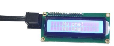
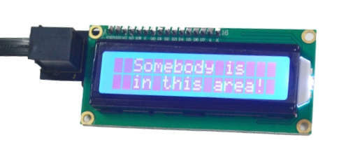
After power is on, when there is no movement near the motion sensor, LCD displays “no one”, and piranha LED is off; when there is someone moving near the motion sensor, LCD will display “somebody is in this area!”, and the LED will be turn on.
Lesson 19: What’s the temperature
In this lesson, we will combine DS18B20 Temperature Sensor and 1602 I2C Module to make a temperature measuring device. You can also apply the experiment principle to make a temperature alarm.
Hardware required
EASY plug controller Board x1
USB cable x1
EASY plug cable x2
EASY plug 1602 I2C Module x1
EASY plug DS18B20 Temperature Sensor x1
Before we get to the test, let’s take a look at this DS18B20 Temperature Sensor.
This DS18B20 Temperature Sensor Module is not like traditional analog temperature sensors that need additional A/D and D/A conversion chip, placing a challenge on limited port resources of Arduino, this newly developped DS18B20 Temperature Sensor can be easily connected to an Arduino digital input. The sensor communicates over a one-wire bus and requires little in the way of additional components so users can easily create a sensor network. Below are its specifications:
Supply Voltage: 3.3V to 5V
Temperature range: -55 °C ~ +125 °C
Interface: Digital
Size: 40*20mm
Weight: 3g
Connection Diagram
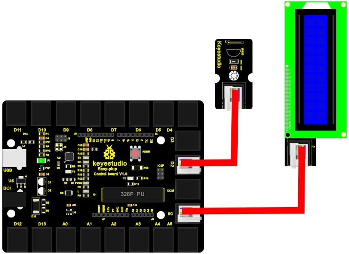
Now, connect the DS18B20 module to the D2 port of the controller board, and LCD module to IIC using the EASY plug cables.
Sample Code
Connect the board to your PC using the USB cable; copy below code into Arduino IDE, and click upload to upload it to your board.
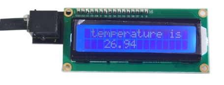
Result After power is on, LCD first line displays “temperature is”, second line displays the current temperature. Temperature is updated in 3 seconds interval.
Lesson 20: How humid & hot is the air
Temperature and humidity is vital to our well beings. In this lesson, we will learn how to measure the temperature and humidity of our surroundings using a DHT11 Temperature and Humidity Sensor and a 1602 LCD.
Hardware required
EASY plug controller Board x1
USB cable x1
EASY plug cable x2
EASY plug 1602 I2C Module x1
EASY plug DHT11 Temperature and Humidity Sensor x1
We will first learn a little about this DHT11 Temperature and Humidity Sensor.
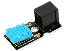
This DHT11 Temperature and Humidity Sensor features a digital temperature and humidity sensor complex with a calibrated digital signal output. It can detect temperature and humidity of the surroundings. It has excellent quality, fast response, anti-interference ability and high cost performance advantages. Below are its specifications:
Supply Voltage: +5 V
Temperature range: 0-50 °C error of ± 2 °C
Humidity: 20-90% RH ± 5% RH error
Interface: Digital
Size: 42*20mm
Weight: 4g
Connection Diagram
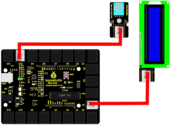
Now, connect the DHT11 module to the D10 port of the controller board, and LCD module to IIC port using the EASY plug cables.
 Sample Code
Connect the board to your PC using the USB cable; copy below code into Arduino IDE, and click upload to upload it to your board.
Result
After power is on, first line of LCD displays “Humid(%),Temp(C)”, second line displays current temperature and humidity. Values will be updated per second.

Last updated
Was this helpful?