OpenELAB 4DOF Mechanical Arm Robot Car Learning Starter Kit
Product Link
Description
Mechanical arm, alike people’s arms, could execute a series of postures. At present, many mechanical arms can’t be operated flexibly because of the change of environment and distance.
On tackling this problem, KEYES group has launched a 3 in 1 learning kit-4DOF mechanical robotic arm car. With this kit, you could acquire how to control mechanical arm and smart car. I believe that you can’t help opening it to get started.
Features
3 in 1 Design: Smart car, mechanical arm, mechanical robot arm car Multi-purpose Function: obstacle avoidance, follow, remote control and automatic convey.
Easy to Build: Soldering circuit is not required.
High Tenacity: high performance baseplate and metal mechanical arm
High Extension: expand other sensors and modules through motor driver shield.
Multiple Controls: PS2 joypad control, fully automatic and App control(iOS and Android system)
Basic Programming:C language code learning.
Specification
Working voltage: 5v
Input voltage: 7-12V
Maximum output current: 3A
Maximum power dissipation: 25W (T=75℃)
Motor speed: 5V 63 rpm / min
Motor drive form: TB6612 drive
Ultrasonic sensing angle: <15 degrees
Ultrasonic detection distance: 2cm-400cm
Bluetooth remote control distance: 20-50 meters (measured)
Bluetooth APP control: support Android and iOS system
Component List
OpenELAB V4.0 Development Board (Compatible Arduino UNO)
1

USB Cable AM/BM Blue OD:5.0 L=1m
1

HC-SR04 Ultrasonic Sensor
1

OpenELAB TB6612FNG Motor/Servo Drive Shield
1

OpenELAB Red LED Module
1

PS2 Wireless 2.4G Game Controller
1

Baseplate for Ultrasonic Sensor/Servo
1


Car BaseplateT=3.0 KS0520
1

Bearing Cap
1


15 pcs Aluminium Alloy Robot Arm Parts
1

18650 2-Slot Battery Holder with Lead
1

OpenELAB Car Wheels
2

4.5V 200rpm Motor
2

AXK Plain Bearing
1

Plain Bearing
2

Universal Wheel
1

Fixed Mount 23155MM
2

M3*30MM Round Head Screws
4
![]()
MG90S 14G Servo
4

M3*10MM Dual-pass Copper Bush
8
![]()
M3*25MM Dual-pass Copper Bush
2

M3*30MM Dual-pass Copper Bush
4

M3*6MM Round Head Nuts
26

![]()
![]()
M3*8MM Round Head Screws
21


![]()
M2.5*10MM Round Head Screws
2

M3*10MM Flat Head Screws
3

![]()
M2*8MM Round Head Screws
4

M2*12MM Round Head Screws
6
![]()
![]()
M2 Nickel Plated Nut
10
![]()
M1.2*4MM Self-tapping Round Head Screws
12
![]()
![]()
M3 Nickel Plated Nut
12

M2.5*20MM Round Head Screws
2

M2.5 Nickel Plated Self-locking Nuts
2
![]()
M3 Nickel Plated Self-locking Nuts
14
![]()
White Insulator
6
![]()
Black Ties 3*100MM
10
![]()
20cm 2.54 3pin F-F Dupont Wire Eco-friendly
2

M-F 15CM/40P/2.54/10Dupont Wire
0.25
![]()
HX-2.54 4P to Dupont Wire 26AWG 200mm
1
![]()
3*40MM Red and Black Screwdriver
1
![]()
2.0*40MM Purple and Black Screwdriver
1
![]()
M2+M3 Wrench
1
![]()
OpenELAB HM-10 Bluetooth-4.0 V3 Module
1

Winding Pipe
1

6-Slot AA Battery Holder with 15CM Lead
1

M1.4 Nickel Plated Nuts
6
![]()
M1.4*8MM Round Head Screws
6
![]()
Getting Started with Arduino
OpenELAB V4.0 Development Board
We need to know OpenELAB V4.0 development board, as a core of this smart car.
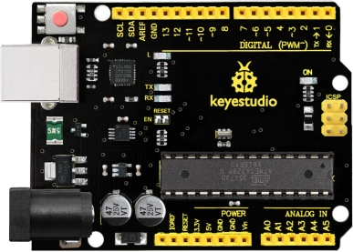
OpenELAB V4.0 development board is an Arduino uno -compatible board, which is based on ATmega328P MCU, and with a cp2102 Chip as a UART-to-USB converter.
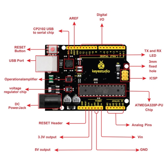
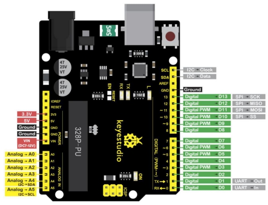
It has 14 digital input/output pins (of which 6 can be used as PWM outputs), 6 analog inputs, a 16 MHz quartz crystal, a USB connection, a power jack, 2 ICSP headers and a reset button.
It contains everything needed to support the microcontroller; simply connect it to a computer with a USB cable or power it via an external DC power jack (DC 7-12V) or via female headers Vin/ GND(DC 7-12V) to get started.
Operating Voltage
5V
Input Voltage (recommended)
DC7-12V
Digital I/O Pins
14 (D0-D13) (of which 6 provide PWM output)
PWM Digital I/O Pins
6 (D3, D5, D6, D9, D10, D11)
Analog Input Pins
6 (A0-A5)
DC Current per I/O Pin
20 mA
DC Current for 3.3V Pin
50 mA
Flash Memory
32 KB (ATmega328P-PU) of which 0.5 KB used by bootloader
SRAM
2 KB (ATmega328P-PU)
EEPROM
1 KB (ATmega328P-PU)
Clock Speed
16 MHz
LED_BUILTIN
D13
Installing Arduino IDE
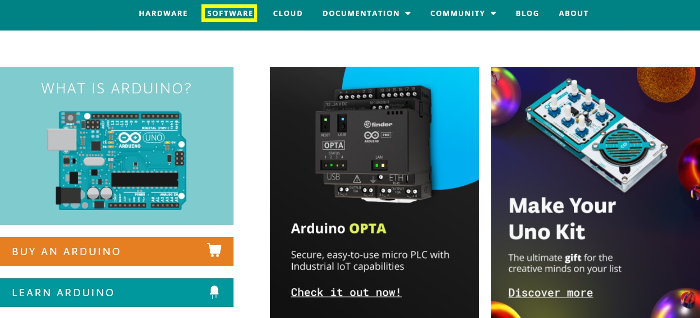
Click the link to start learning how to download software, install drivers, upload code, and install library files.
https://getting-started-with-arduino.readthedocs.io
Projects
Project 1 LED Light
(1)Description

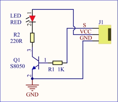
For the starter and enthusiast, this is a fundamental program---LED Blink. LED, the abbreviation of light emitting diodes, consist of Ga, As, P, N chemical compound and so on. The LED can flash diverse colors by altering the delay time in the test code. When in control, power on GND and VCC, the LED will be on if S end is high level; nevertheless, it will go off.
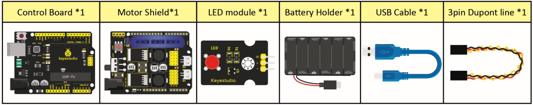
(2)What You Need
(3)Specification
Control interface: digital port
Working voltage: DC 3.3-5V
Pin spacing: 2.54mm
LED display color: red
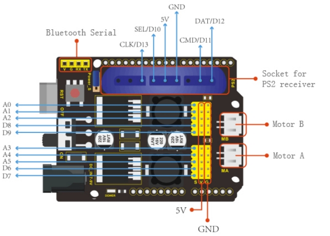
(4)Pins of Motor Driver Shield
(5)Connection Diagram:
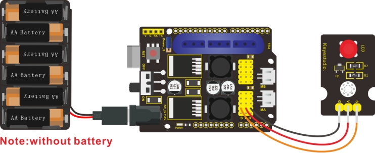
The pin -, + and S are connected to G(GND), V(5V) and S(D6) of shield.
(6)Test Code:
(7)Test Result:
Upload the program, LED flickers with the interval of 1s.
(8)Code Explanation:
pinMode(ledPin,OUTPUT) - This function denotes that the pin is INPUT or OUTPUT.
digitalWrite(ledPin,HIGH) - When pin is OUTPUT, we can set it to HIGH(output 5V) or LOW(output 0V)
(9)Extension Practice:
We succeed to blink LED. Next, let’s observe what LED will change if we modify pins and delay time.
The LED flickers faster through the test result, therefore, delaying time could affect flash frequency.
7.Question
Last updated
Was this helpful?