OpenELAB EASY PLUG Ultimate Starter Kit for Arduino
Product Link
Kit Description
The OpenELAB EASY PLUG ultimate starter kit is based on Mixly blocks coding, very easy to use and flexible. This kit includes everything you need to complete Mixly projects that will teach you how to control and read external sensors and displays, sound control, learn Mixly Blocks programming, and much more. These boards and modules are the best to start learning and tinkering with electronics and coding. The Starter Kit includes a user guide with 22 tutorials that will walk you through the basics up to complex projects. Although you have a few or even no electronics related knowledge, you can use this kit to realize your creative ideas as long as you want to. After using this kit you’ll have the know-how to start creating your own amazing experiments. Share your own creative works with your intimate family, friends or classmates. Let’s get started right now!
Kit List
1
EASY plug Control Board V2.0
1

2
EASY plug Green LED Module
1

3
EASY plug Yellow LED Module
1

4
EASY plug Red LED Module
1

5
EASY plug Passive Buzzer Module
1

6
EASY plug Photocell Sensor
1

7
EASY plug Soil Humidity Sensor
1

8
EASY plug Analog Gas Sensor
1

9
EASY plug TEMT6000 Ambient Light Sensor
1

10
EASY plug slide potentiometer module
1

11
EASY plug Capacitive Touch Sensor
1

12
EASY plug Knock Sensor
1

13
EASY plug Flame Sensor Module
1

14
EASY plug PIR Motion Sensor
1

15
EASY plug DS18B20 Temperature Sensor
1

16
EASY plug IR Receiver Module
1

17
EASY plug Infrared Obstacle Detector Sensor
1

18
EASY plug DS3231 Clock Module
1

19
EASY plug Joystick Module
1

20
EASY plug SR01 Ultrasonic Module
1

21
EASY plug OLED Module
1

22
EASY plug L9110 Fan Motor Module
1

23
EASY plug Servo Module
1

24
OpenELAB 9G blue Micro Servo 90°
1

25
EASY plug 2812 2x2 full-color RGB Module
1

26
200mm blue RJ11 cable
5

27
300mm blue RJ11 cable
3

28
USB cable
1

29
Acrylic Board
1

30
Dual-pass M3*15MM Copper Pillars
1

31
M3*10MM Round Head Screws
1
![]()
Install Mixly and Driver
Download Mixly
Mixly
Mixly is a free open-source graphical Arduino programming software, based on Google’s Blockly graphical programming framework, and developed by Mixly Team@ BNU. It is a free open-source graphical programming tool for creative electronic development; a complete support ecosystem for creative e-education; a stage for maker educators to realize their dreams. Although there is an Ardublock graphical programming software launched by Arduino official, Ardublock is not perfect enough, and many common functions cannot be realized.
②Download and install Mixly1.0 software
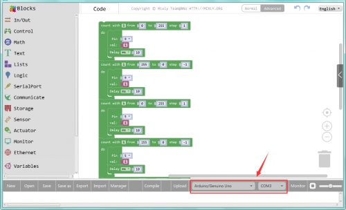
Windows version: We will take Mixly1.0 (Windows version) as example. Install Software: You will get installation package after downloading. As shown below:

Unzip the package, you will see “Mixly 1.0 for OpenELAB.exe”
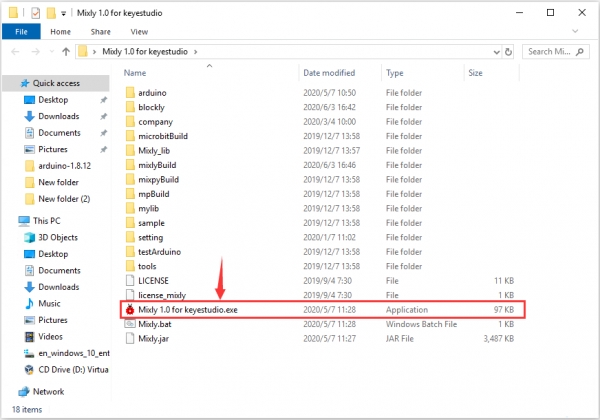
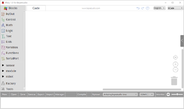
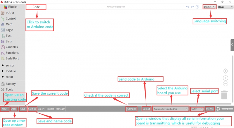
Double-click ”Mixly 1.0 for OpenELAB.exe”, the following interface pops up.
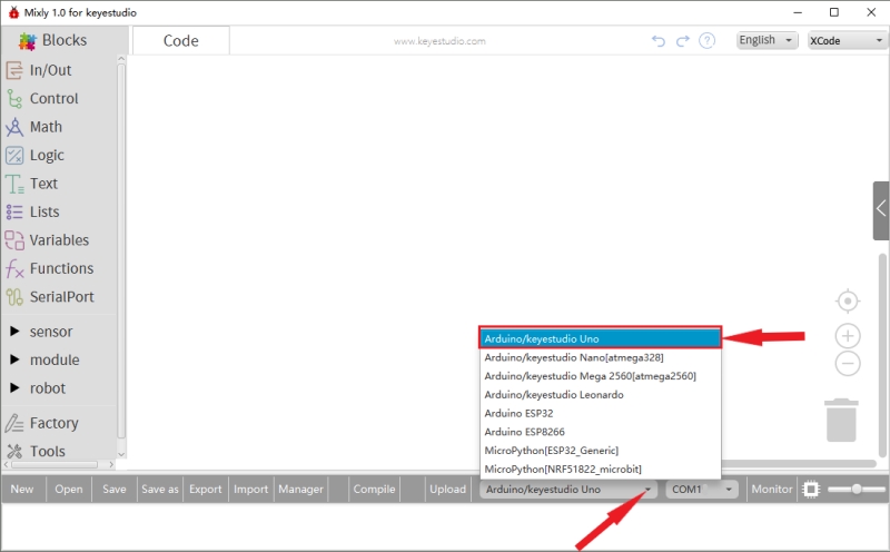
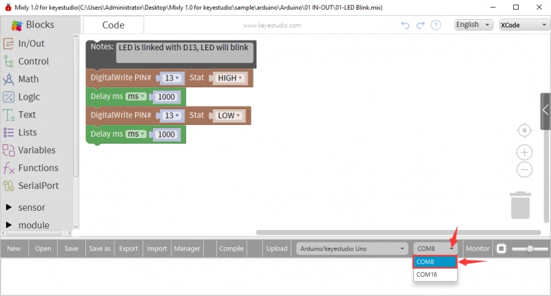
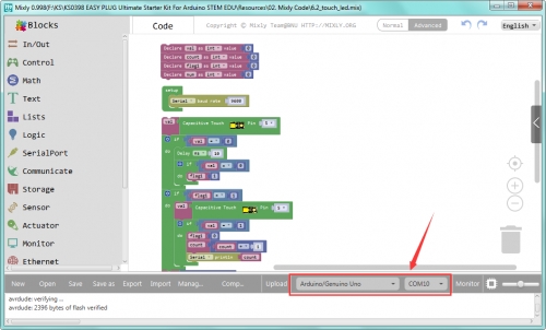
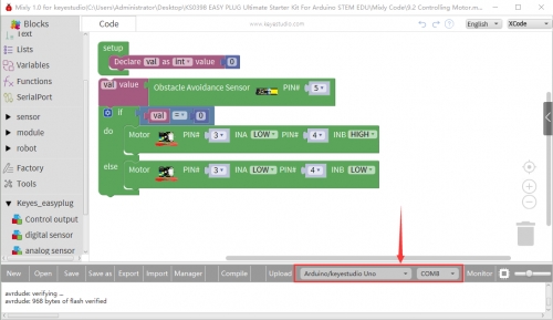
We have to choose correct Arduino development board and name, as shown below:
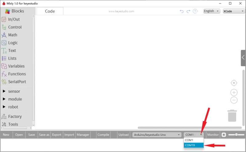
Select correct COM port(the corresponding port will be shown after installing driver successfully)
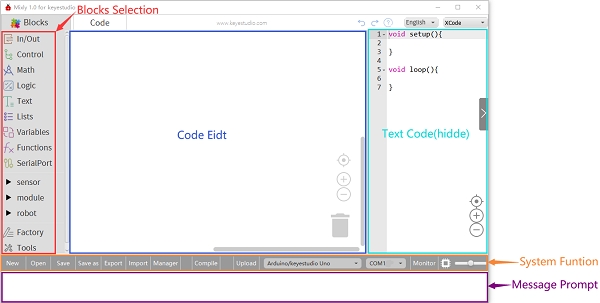
You have to know the function of every area and interface on Mixly software before uploading program on Arduino development board.
Install the driver of the development board
Next, we will introduce the driver of the development board. The driver installation may have slight differences in different computer systems. So in the following let’s take an example of the driver installation in the WINDOWS system.
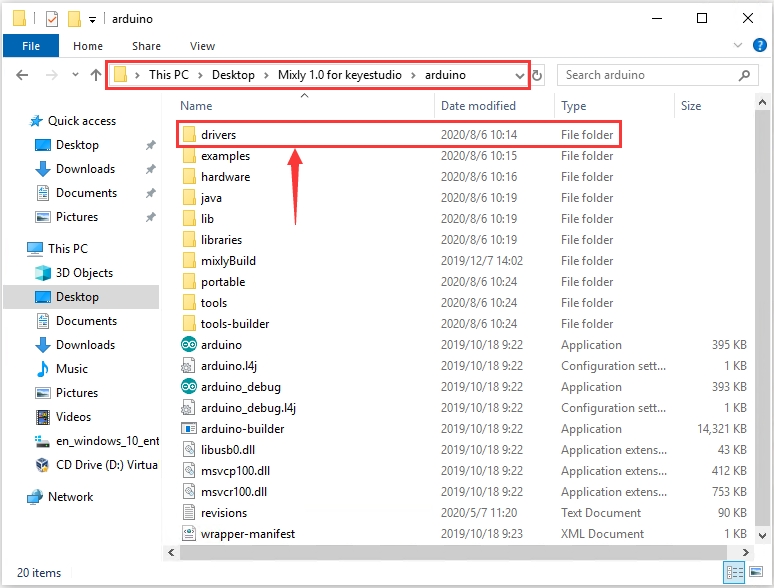
Mixly 1.0 for OpenELAB folder contains its software and driver files. Before we launch the Mixly software, you only need to install the USB drivers.
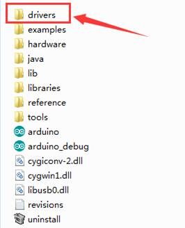
Double-click the Mixly 1.0 for OpenELAB folder—> arduino—>drivers
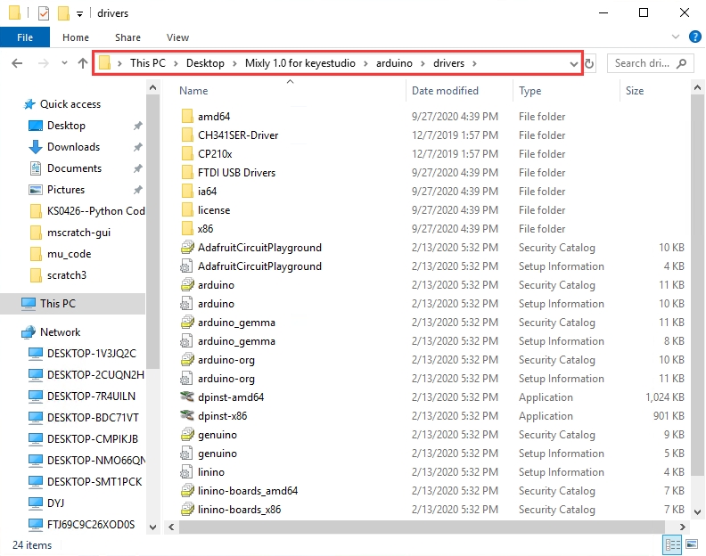
The driver files are shown below:
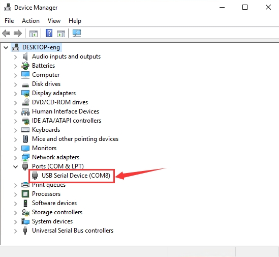
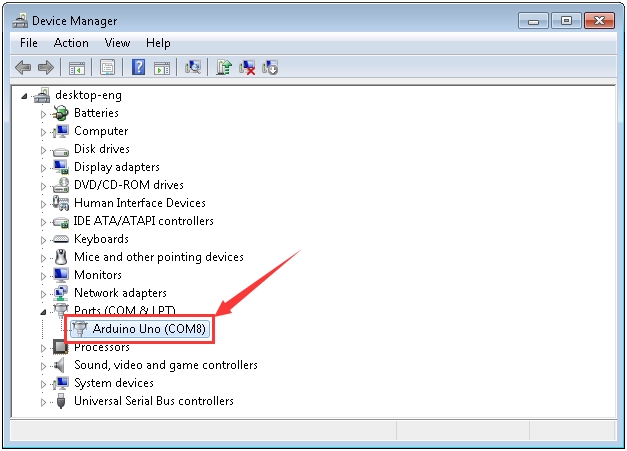
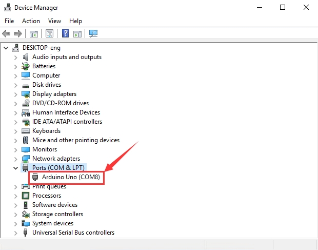
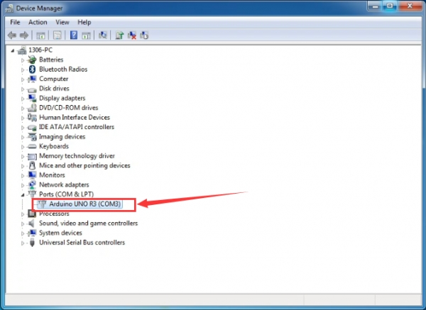
Connect the EASY Plug control board V2.0 to the computer with a USB cable. Right click the icon of your“Computer”—>“Properties”—>“Device manager”.
If your computer is Windows10, the USB Serial Device(COM8) will be shown. That indicates that the USB driver is installed. But for other systems like Windows 7 or 8, you may have to install the USB driver manually.
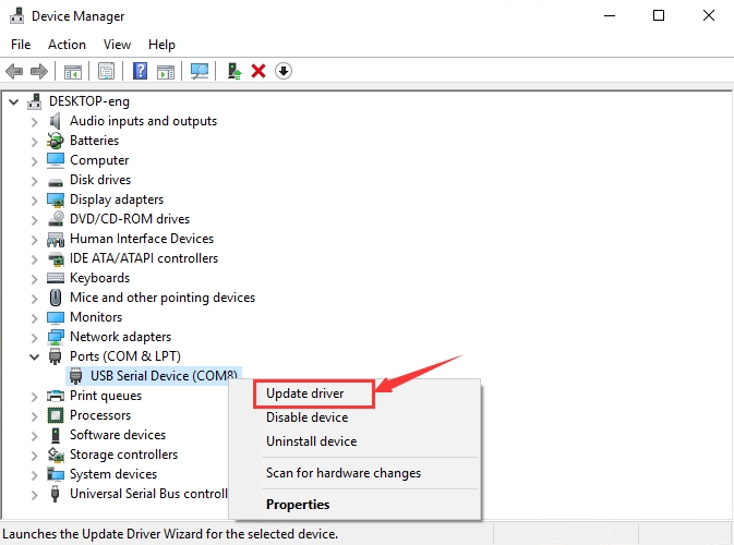
Right-click USB Serial Device(COM8) to select Update driver
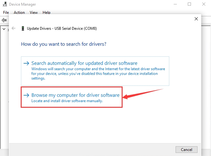
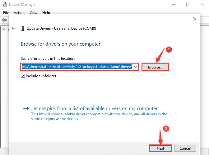
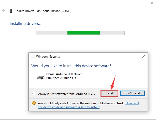
Click “browse my computer for updated driver software”, find out the drivers folder and enter “driver” to search in rectangular box. Click “Next”, the driver will be installed successfully.
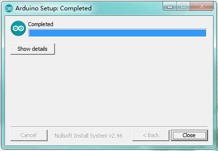
Click Install to wait for the installation
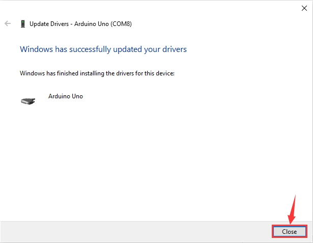
Click Close and you can see the following device in the Device Manager.
If your computer is Windows7/8, please follow our instruction.
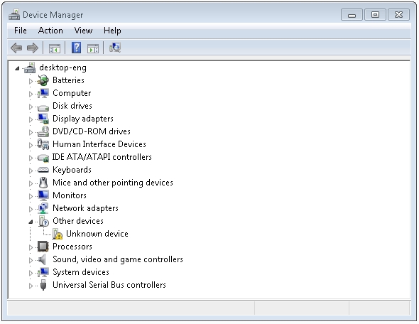
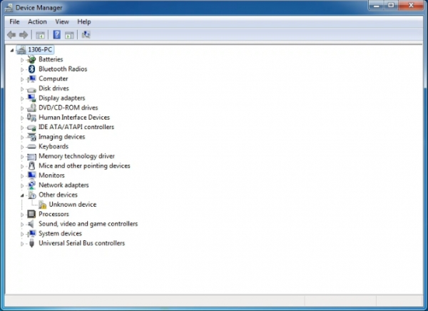
When you connect the board to your computer at the first time, right-click the icon of your “Computer” —>for “Properties”—> click “Device manager”, under “Other Devices”, you should see an icon for “Unknown device” with a little yellow warning triangle next to it.
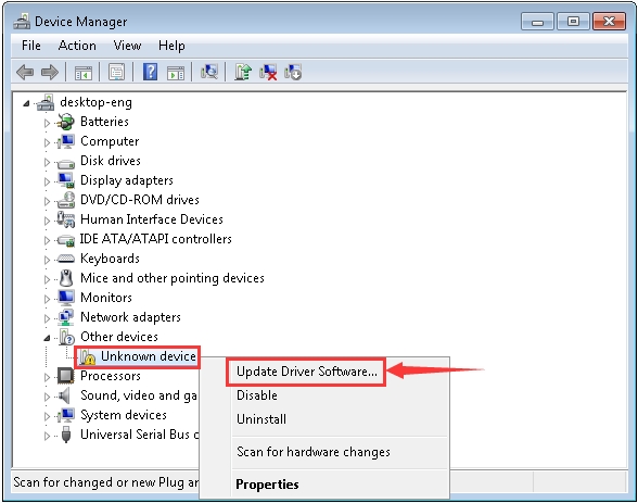
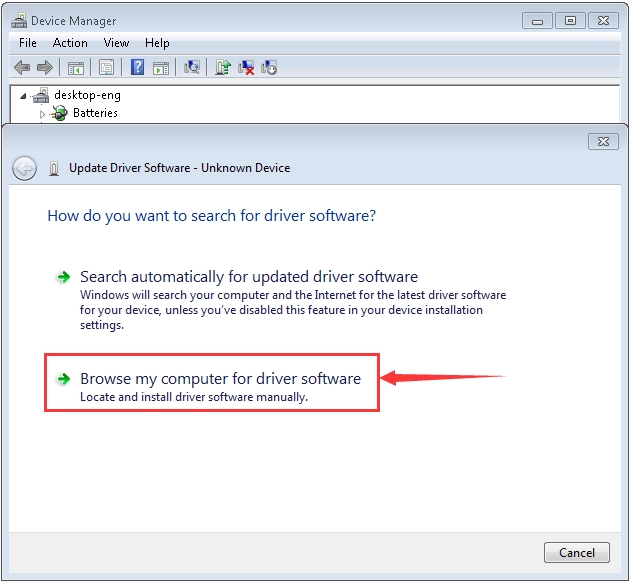
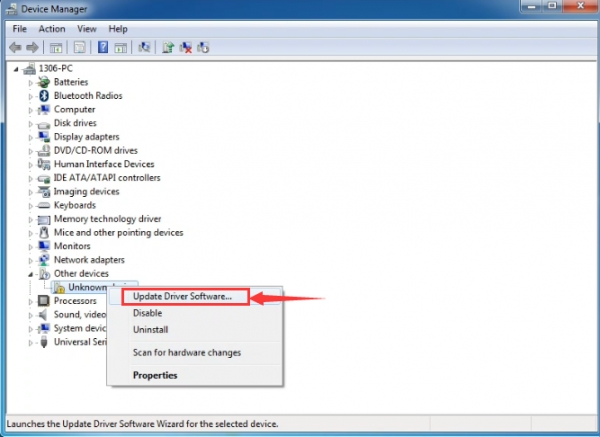
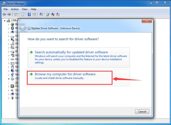
Then right-click on the device and select the top menu option (Update Driver Software...) shown as the figure below.
It will then be prompted to either “Search Automatically for updated driver software” or “Browse my computer for driver software”. Shown as below. In this page, select “Browse my computer for driver software”.
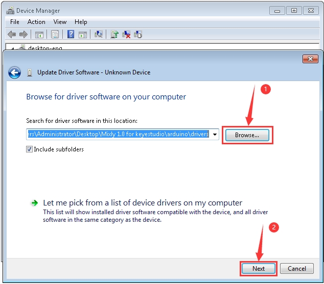
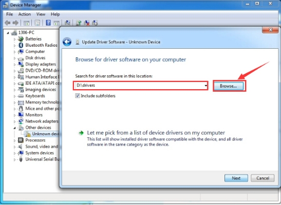
Click “Browse”, then find out the drivers folder and enter “driver” to search in rectangular box. Click “Next”, the driver will be installed successfully. (I place Arduino software folder on the desktop, you could follow my way)
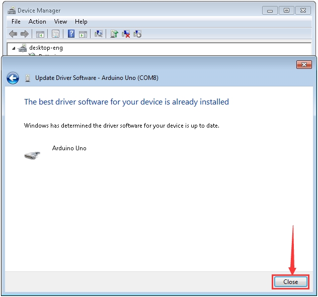
The driver of your device is already installed.
Click“Close”
Up to now, the driver is installed well. Then you can right click “Computer” —>“Properties”—>“Device manager”, you should see the device as the figure shown below
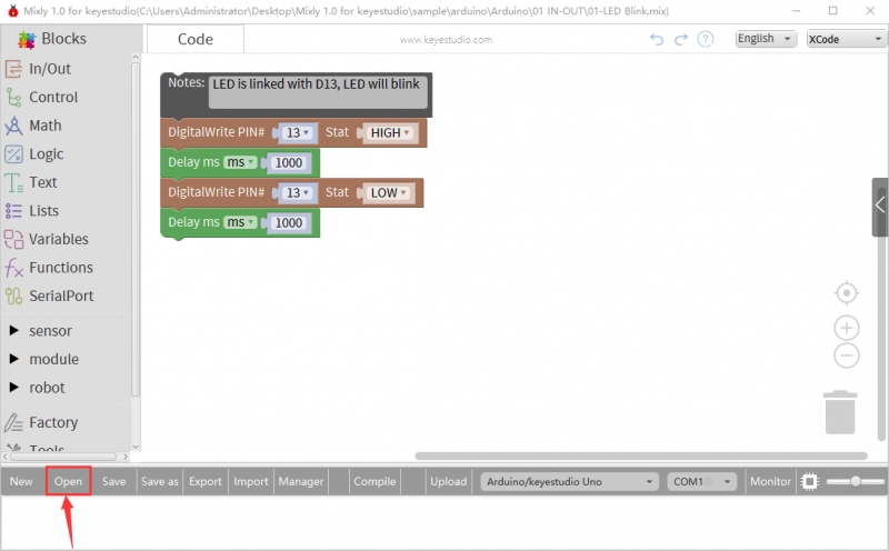
Start the first program
Click “Open”→ sample → arduino→ Arduino → 01 IN-OUT→01-LED Blink.mix
We have to choose correct Arduino development board and name, as shown below:
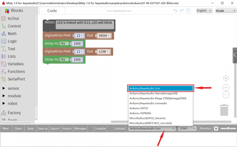
The corresponding board and COM port will be shown after setting board and COM port.
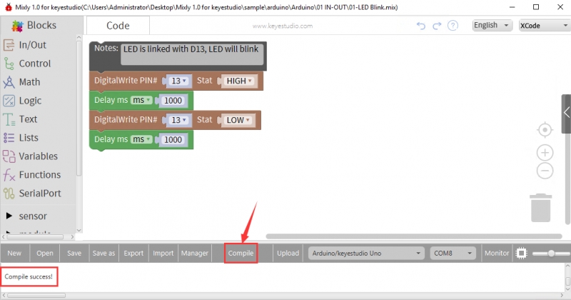
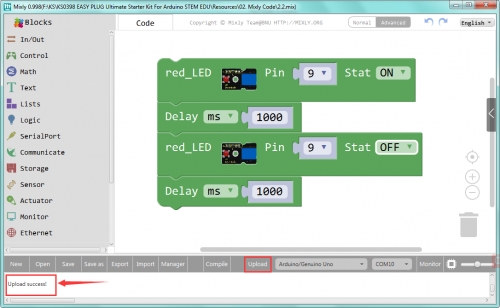
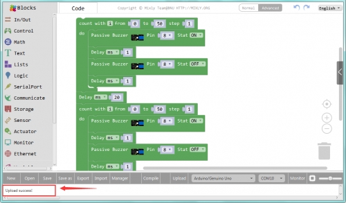
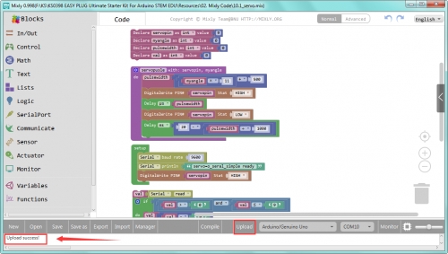
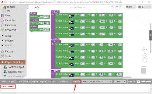
Click Upload to upload the program

Upload successfully. After uploading the program successfully, the onboard LED lights up for 1s, lights off for 1s.
Import the Library
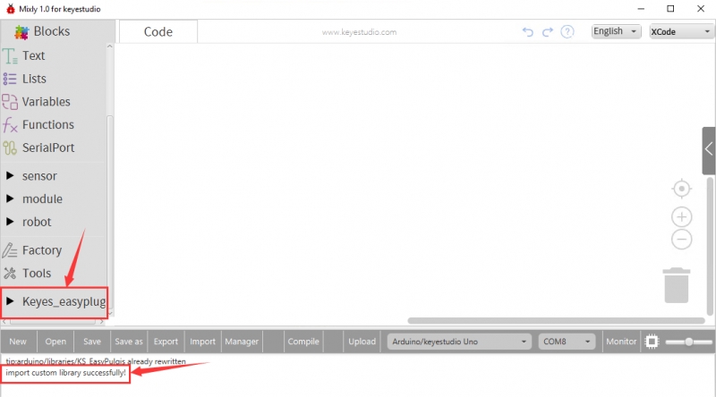
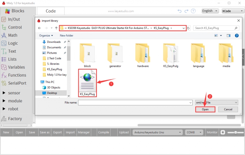
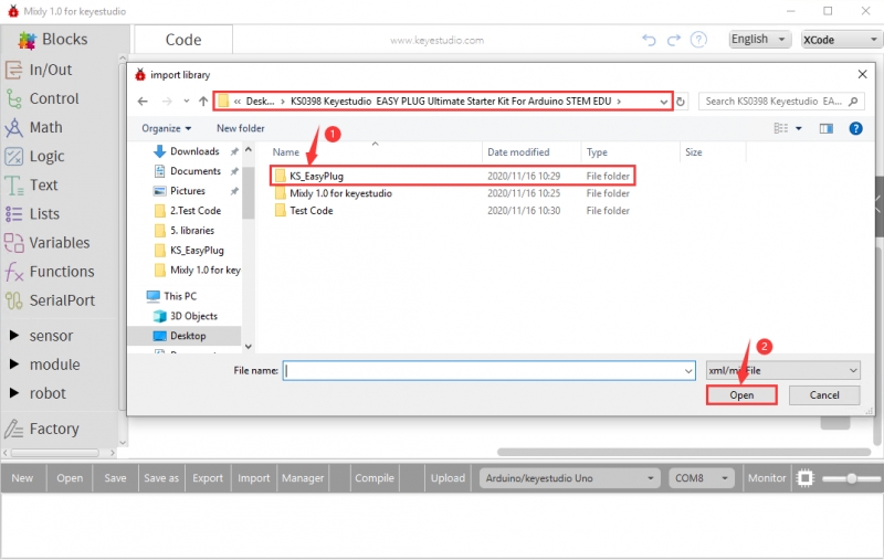
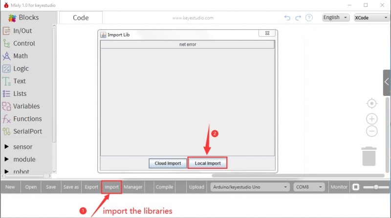
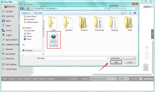
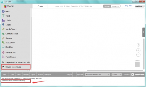
Open Mixly 1.0 for OpenELAB software, click“Import”then select“Local import”, as shown below: Double-click the folder“KS_EasyPulg”and select“KS_EasyPulg”library file After importing it, you will see it in the blocks list. Also, the interface will show “import custom library successfully!”
Installing Arduino Software
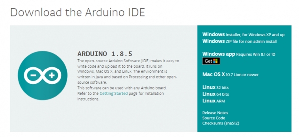
When you get the control board, first you should install the Arduino software and driver. We usually use the software Arduino 1.5.6 version. You can download it from the link below: https://www.arduino.cc/en/Main/OldSoftwareReleases#1.5.x Or you can browse the ARDUINO website to download the latest version from this link, https://www.arduino.cc, pop up the following interface.

Then click the SOFTWARE on the browse bar, you will have two options ONLINE TOOLS and DOWNLOADS.

Click DOWNLOADS, it will appear the latest software version of ARDUINO 1.8.5 shown as below.
In this software page, on the right side you can see the version of development software for different operating systems. ARDUINO has a powerful compatibility. You should download the software that is compatible with the operating system of your computer. We will take WINDOWS system as an example here. There are also two options under Windows system, one is installed version, the other is non-installed version. For simple installed version, first click Windows Installer, you will get the following page.

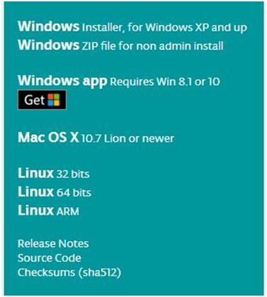
This way you just need to click JUST DOWNLOAD, then click the downloaded file to install it. For non-installed version, first click Windows ZIP file, you will also get the pop-up interface as the above figure. Click JUST DOWNLOAD, and when the ZIP file is downloaded well to your computer, you can directly unzip the file and click the icon of ARDUINO software to start it.
Installing Arduino (Windows)
Install Arduino with the exe. Installation package downloaded well.
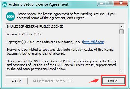
Click“I Agree”to see the following interface.
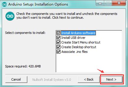
Click “Next”. Pop up the interface below.
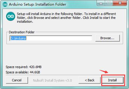
You can press Browse… to choose an installation path or directly type in the directory you want. Then click “Install” to initiate installation.
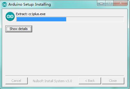
Wait for the installing process, if appear the interface of Window Security, just continue to click Install to finish the installation.
Installing Driver
Next, we will introduce the driver installation of UNO R3 development board. The driver installation may have slight differences in different computer systems. So in the following let’s move on to the driver installation in the WIN 7 system. The Arduino folder contains both the Arduino program itself and the drivers that allow the Arduino to be connected to your computer by a USB cable. Before we launch the Arduino software, you are going to install the USB drivers.
Plug one end of your USB cable into the Arduino and the other into a USB socket on your computer. When you connect UNO board to your computer at the first time, right click the icon of your “Computer” —>for “Properties”—> click the “Device manager”, under “Other Devices”, you should see an icon for “Unknown device” with a little yellow warning triangle next to it. This is your Arduino.
Then right-click on the device and select the top menu option (Update Driver Software...) shown as the figure below..
It will then be prompted to either “Search Automatically for updated driversoftware” or “Browse my computer for driver software”. Shown as below. In this page, select “Browse my computer for driver software”.
After that, select the option to browseand navigate to the “drivers” folder of Arduino installation.
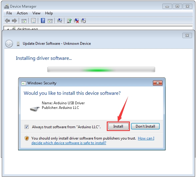
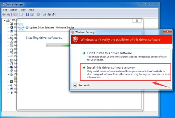
Click “Next” and you may get a security warning, if so, allow the software to be installed. Shown as below.
Once the software has been installed, you will get a confirmation message. Installation completed, click “Close”.
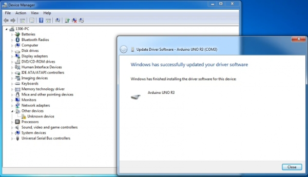
Up to now, the driver is installed well. Then you can right click “Computer” —>“Properties”—>“Device manager”, you should see the device as the figure shown below.
Let’s Get Started With Your Projects
Project 1: Hello World
Overview

This project is very simple. You can use only a main board and a USB cable to display the “Hello World!”. It is a communication experiment between the EASY Plug control board and PC. This is an entry experiment for you to enter the Arduino programming world. Note that need to use a serial communication software, Arduino IDE. In the above part, you can check the detailed use of Arduino IDE. Component Required:
EASY plug control board*1
USB cable*1
Component Introduction:
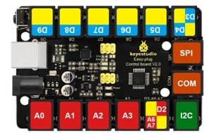
The processor used in OpenELAB EASY plug control board V2.0 is ATmega328. It has 5 single Digital ports labeled D5 to D9 (of which 3 can be used as PWM outputs), 1 dual-digital interface (D3-D4), 4 analog inputs (A0-A3), a Joystick socket (D2-A6-A7), a SPI, a serial port and an IIC communication interface. Also with a USB connection, a power jack, two ICSP headers and a reset button. It breaks out the IO ports with RJ11 6P6C plug.
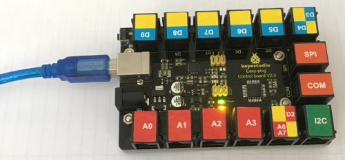
Connect It Up Connect the control board to your computer via a micro USB cable.
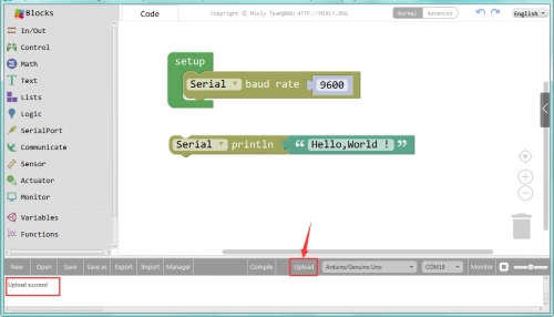
Upload the Code Below is an example code for displaying the Hello World!
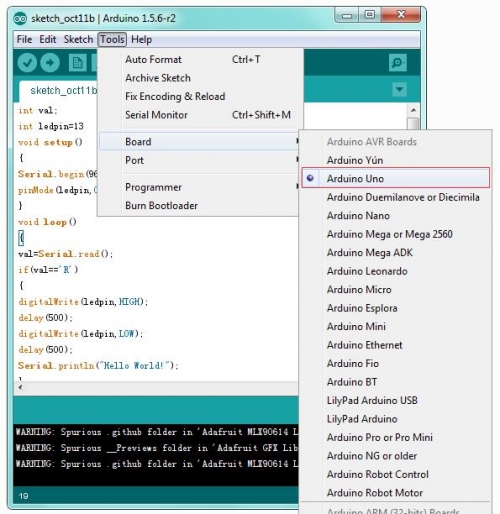
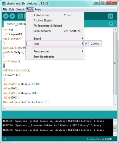
Select the Arduino Board Open the Arduino IDE, you’ll need to click the “Tools”, then select the Board that corresponds to your Arduino.
Select your serial port
Select the serial device of the Arduino board from the Tools | Serial Port menu.
Note: to avoid errors, the COM Port should keep the same as the Ports shown on Device Manager.

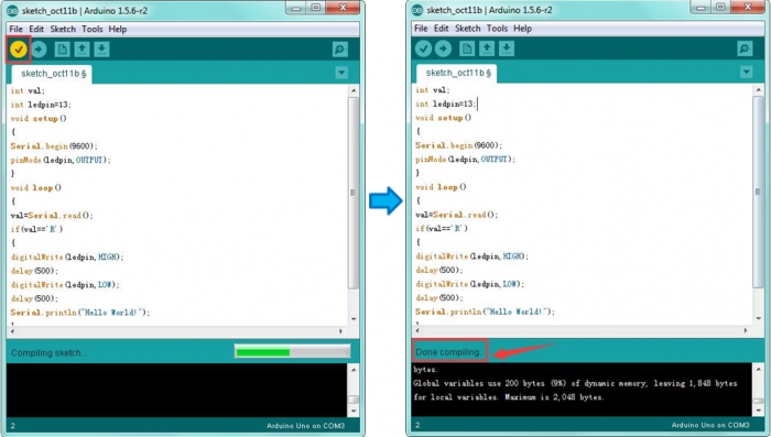
 Then click verify button to check the errors. If compiling successfully, the message "Done compiling" will appear in the status bar.
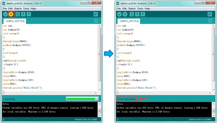
After that, click the “Upload” button to upload the code. If the upload is successful, the message "Done uploading" will appear in the status bar.
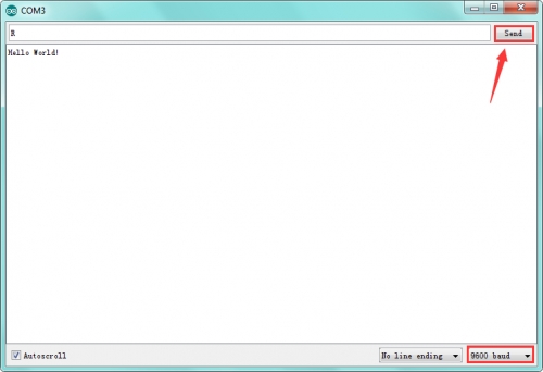
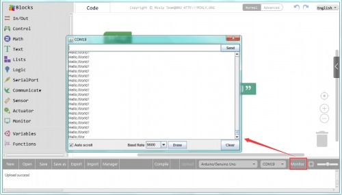
Open the Serial Monitor After that, click the monitor button to open the serial monitor.
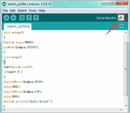
Then set the baud rate to 9600, enter an “R” and click Send, you should see the RX led on the board blink once, and then D13 led blink once, finally "Hello World!" is showed on the monitor, and TX led blink once. Congrats! Your first simple program is complete.
Note: In this project, we take Arduino code as an example to show Hello World. But in the following projects, we will take Mixly Code as example to start the experiments. It will be more simple and easier for you to get understand of the program.
How To Get Started With Mixly Projects
Import the Library
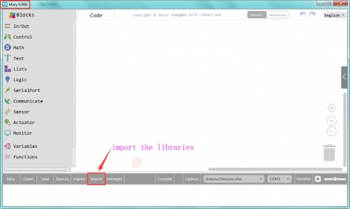
1) Begin with the Mixly projects, the first step you should import the corresponding library. Open the Mixly 0.998 software, click Import. Shown below.
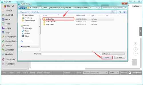
2) Open the folder we provided, you can double-click to open the library KS_EasyPulg
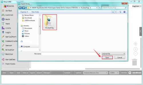
3) If import the custom library successfully, you should see it on the Mixly blocks interface. Shown below.
Start with Mixly Project - Saying Hello World
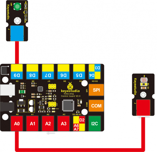
1) Hookup Guide Connect the control board to your computer via a micro USB cable.
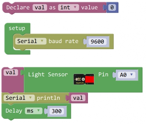
2) Open the Program Click Open to open your first program Hello World. Follow the steps below.
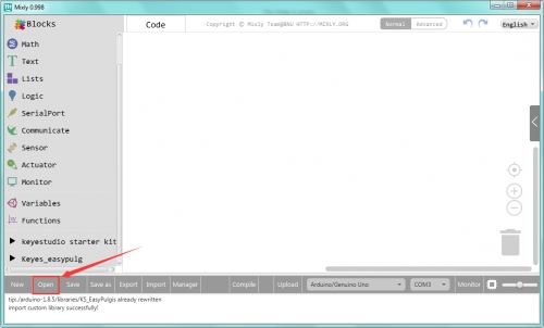
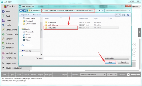
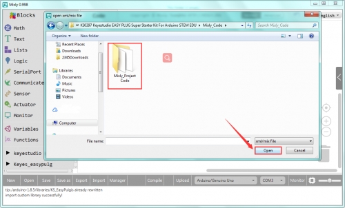
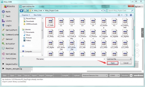
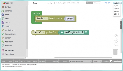
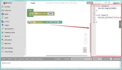
In fact, you can double click or directly drag the program to open Hello World. Then you should see the Blocks code, shown below.
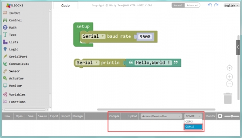
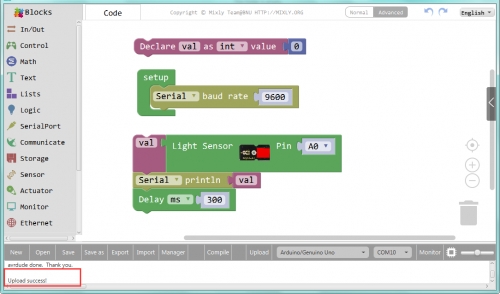
After that, select the proper Board and Port. Upload the code to your EASY Plug control board.
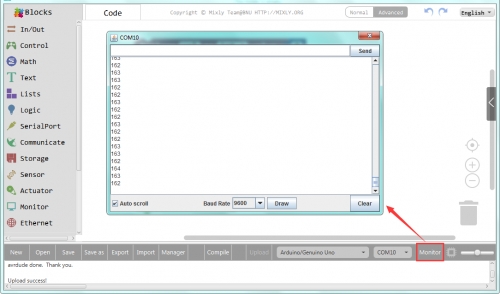
3) Displaying Hello World Finally, upload the code successfully, open the monitor and set the baud rate to 9600, you should be able to see the Hello World is showed on the monitor. Congrats! You make it !
4) Check Arduino Code What’ more, you can also click to check the Arduino code on the right side. Amazing! So powerful the Mixly blocks code is!
Is it more easy and simple to play the Mixly projects? Try your first Mixly blocks projects right now. Begin with the following projects to motivate your creations!
Project 2: LED Light
Overview To start off the EASY Plug sensor module, we will work on an LED. That’s right - it is as simple as turning a light on and off. It might not seem like much, but establishing this important baseline will give you a solid foundation as we work toward more complex experiment.
Component Required
EASY plug control board*1
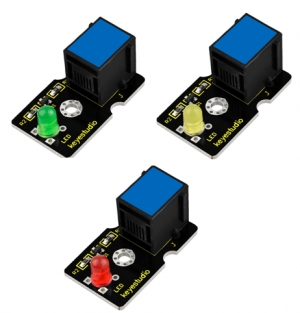
EASY plug LED Module *3
RJ11 cable*1
USB cable*1
Component Introduction: The LED light modules have shiny colors, ideal for Arduino starters. It can be easily connected to IO/Sensor shield. Note: this module needs to be used together with EASY plug control board. You can also choose other LED to emit different color of light like blue, green, yellow and red.
Sensor type: Digital
Interface: Easy plug
PH2.54 socket
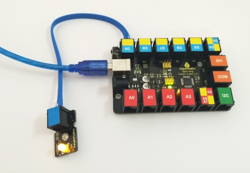
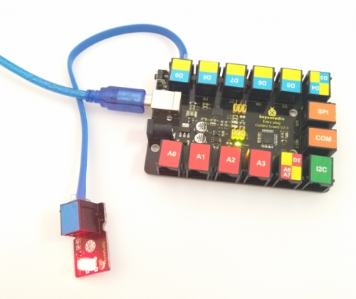
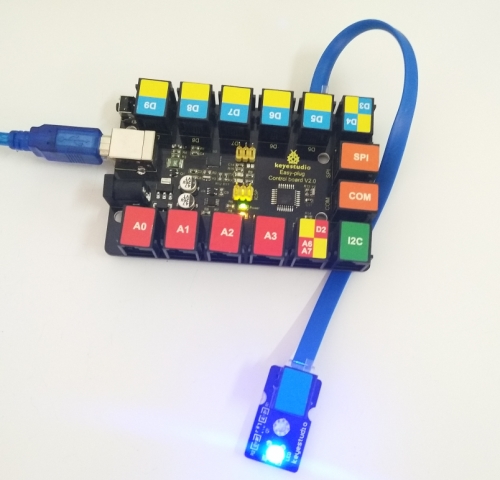
Connect It Up Connect the EASY Plug LED module to control board using an RJ11 cable.
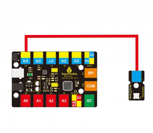
Example 1: Light up LED
Upload the Code Below is an example code for lighting up an LED.
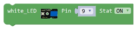
What You Should See The LED is turned on. If it doesn’t, make sure you have assembled the circuit correctly and verified and uploaded the code to your board.
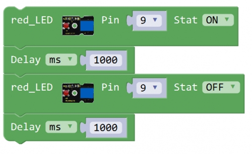
Example 2: LED Blink
Upload the Code Below is an example code for LED blinking.
What You Should See
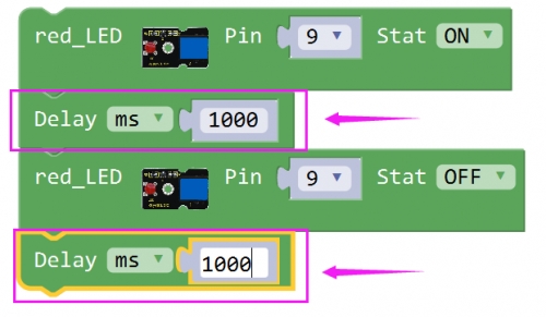
The LED will flash on for one second, then blink off for one second.
If it doesn’t, make sure you have assembled the circuit correctly and verified and uploaded the code to your board.
Little Knowledge: If you want to make the LED flash on and off more quickly or slowly, you can modify the Delay time here.
Thank you! Enjoy the following programming.
Example 3: LED Breath
Here do you know how to connect the LED module? Check the code. Test Code Below is an example code for one LED breathing.
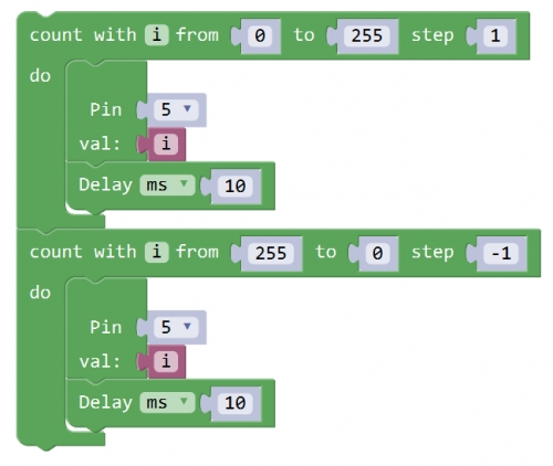
Little Knowledge: Here no connection diagram, which port should you choose? Yeah, Pin 5. See the code, you can modify the connection pin here.
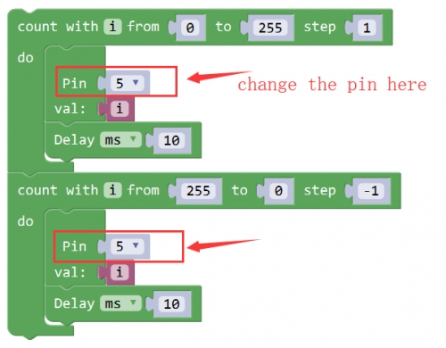
What You Should See The LED gradually becomes brighter for one second, then gradually dimming for one second.
If it doesn’t, make sure you have assembled the circuit correctly and verified and uploaded the code to your board.
Example 4: Brighten and Dim
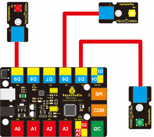
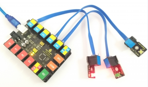
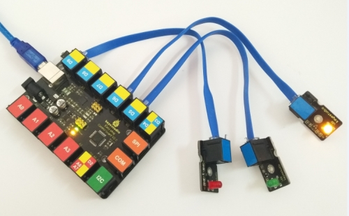
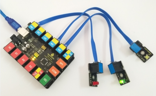
Hookup Guide Connect the three EASY Plug LED modules to control board using RJ11 cables. Connect a red LED to D9, white LED to D6, blue LED to D5.
Upload the Code Below is an example code for three LED modules experiment.
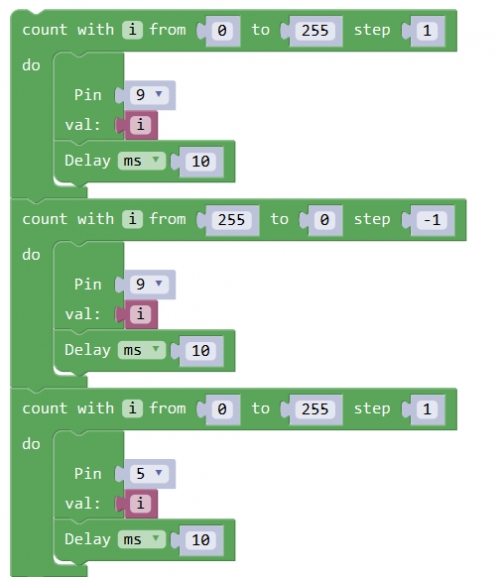
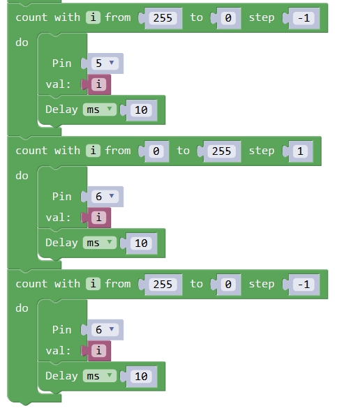
What You Should See The three LEDs are gradually brighter then gradually off one by one, circularly. If it doesn’t, make sure you have assembled the circuit correctly and verified and uploaded the code to your board.
Troubleshooting
LED Not Lighting Up?
If upload the code successfully, but LED still not lights up. Make sure your board and LED module are connected correctly.
Program Not Uploading?
This happens sometimes, the most likely case is a confused Board and serial port, you should firstly select your proper board and port.
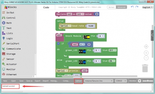
Project 3: Knocking
Overview If you want to build a line tracking robot, the easiest way is to use a line tracking sensor. Line following is the most basic function of smart mobile robot. We designed this new generation of line tracking sensor to be your robot's powerful copilot all the way. It will guide your robot by telling white from black quickly and accurately, via TTL signal. We will make a simple experiment, testing the knock sensor.
Component Required
EASY plug control board*1
EASY plug Knock Sensor *1
RJ11 cable *2
USB cable*1
Component Introduction
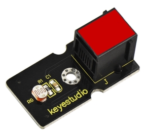
EASY plug Knock Sensor
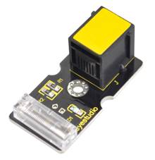
The knock sensor is mainly composed of SW-280 vibration switch, which is an inductive proximity switch. It is an electronic switch that transmits the sensing result to the circuit device and induces the circuit to start working when the vibration force is induced. The module comes with a positioning hole for you to fix it to other devices. You can make full use of it with creative thinking, like electronic drum, and so on.
Connector: Easy plug
Working voltage: 5V
Sensor type: Digital
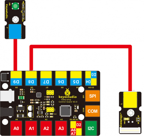
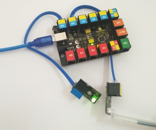
Connect It Up Connect the EASY Plug knock sensor to control board using an RJ11 cable.
Upload the Code
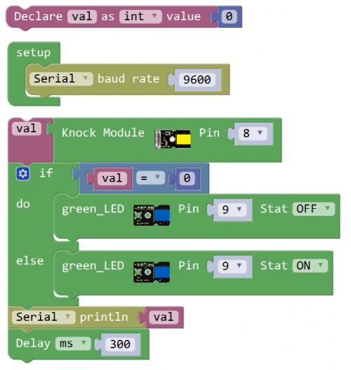
What You Should See Done uploading the code, if knock the module hard, the led will be turned on.
Project 4: How much light
Overview In this project, you’ll be using a photo resistor module, which changes resistance based on how much light the sensor receives.
Component Required
EASY plug control board*1
EASY plug Photocell Sensor *1
EASY plug LED module*1
RJ11 cable *2
USB cable*1
Component Introduction
EASY plug Photocell Sensor
A photoresistor or light-dependent resistor (LDR) or photocell is a light-controlled variable resistor. The principal is very simple. The resistance of photoresistor varies with incident light intensity. If the incident light intensity is high, the resistance decreases; if the light intensity is low, the resistance increases. OpenELAB EASY Plug photocell sensor is a semiconductor, integrated with a photoresistor, easy to use and very convenient for wiring. It has features of high sensitivity, quick response, spectral characteristic and R-value consistence. It can be applied in light-sensitive detector circuits, intelligent switch design and light- and dark-activated switching circuits.
Interface: Easy plug
Working voltage: 5V
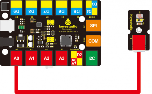
Connect It Up Connect the EASY Plug photocell sensor to control board using an RJ11 cable.
Upload the Code
What You Should See Done uploading the code, you should see the analog value change in accordance with how much light your photoresistor is sensing.
Controlling light brightness
Hookup Guide Connect the EASY Plug photocell sensor and LED module to control board using RJ11 cable.
Test Code Below is an example code for three LED modules experiment.
What You Should See The three LEDs are gradually brighter then gradually off one by one, circularly. If it doesn’t, make sure you have assembled the circuit correctly and verified and uploaded the code to your board.
Project 5: Buzzer clicking
Overview In this project, we’ll bridge the gap between the digital world and the analog world. We’ll be using a buzzer module that makes a small “click” when you apply voltage to it (try it!).
Component Required
EASY plug control board*1
EASY plug Passive Buzzer Module*1
RJ11 cable*1
USB cable*1
Component Introduction
EASY plug Passive Buzzer Module
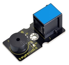
We can use Arduino to make many interactive works of which the most commonly used is acoustic-optic display. The buzzer we introduced here is a passive buzzer. It cannot be actuated by itself, but by external pulse frequencies. Different frequencies produce different sounds. You can use Arduino to code the melody of a song, which is quite fun and simple.
Interface: Easy plug
Working voltage: 3.3-5v
Sensor type: digital
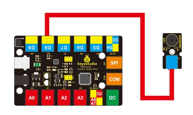
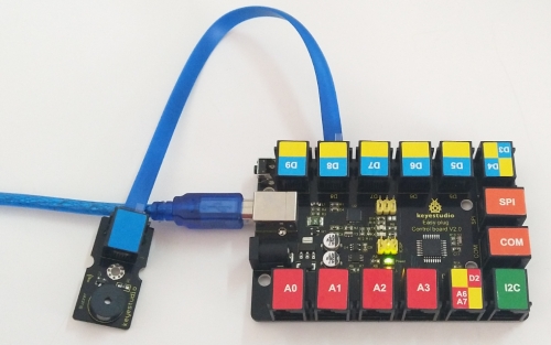
Connect It Up Connect the EASY Plug passive buzzer module to control board using an RJ11 cable.
Upload the Code
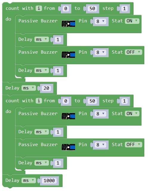
What You Should See Done uploading the code, you should be able to hear the buzzer module make a small “click”.
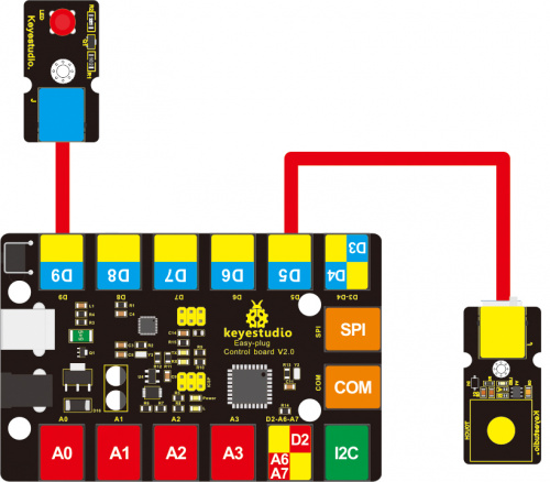
Project 6: Capacitive Touch
Overview Are you tired of clicking mechanic buttons? Well, try our capacitive touch sensor. In this project, we’ll use the EASY Plug touch sensor to make a simple test.
Component Required
EASY plug control board*1
EASY plug Touch Sensor *1
EASY plug LED Module *1
RJ11 cable *2
USB cable*1
Component Introduction
EASY plug Capacitive Touch Sensor
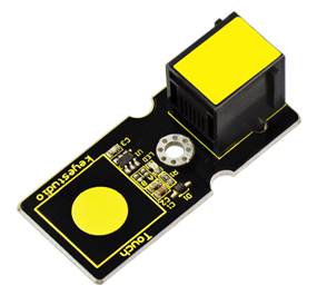
You can find touch sensors mostly on electronic device. Instead of buttons, upgrade your Arduino project with our new version touch sensor and make it cool! This EASY Plug digital capacitive touch sensor provides a one-touch style switch on your Arduino project. It uses the most popular capacitive sensing technology which is the same as your mobile phone. This little sensor can "feel" people and metal touch and feedback a high/low voltage level. Even isolated by some cloth and paper, it can still feel the touch. The sensitivity will decrease as the isolation getting thick.
Supply Voltage: 3.3V to 5V
Sensor type: Digital
Function range: 0℃ to 100℃
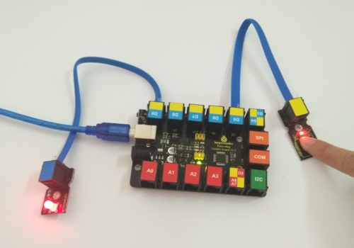
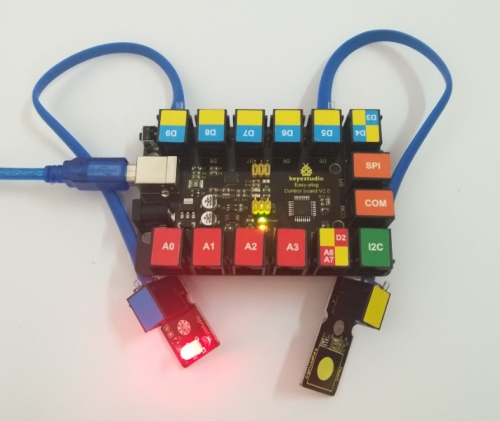
Connect It Up Connect the EASY Plug touch sensor and LED module to control board using RJ11 cable.
Test Code Below is an example code.
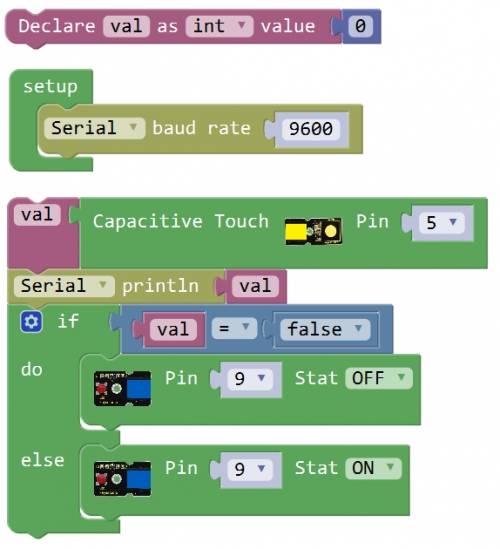
What You Should See Done uploading the code, when you touch the sensor, the led on the sensor will light up.
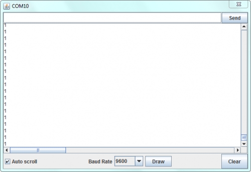
Open the monitor, it will print out the value read from the touch sensor.
Simulating Table Lamp
Test Code
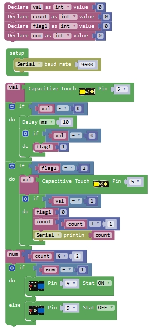
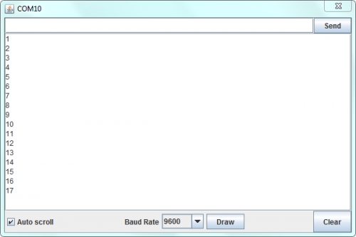
What You Should See Powered up and upload well the code, press down the button, LED light is turned on, it will not be off when release the button; But if press the button once again, LED will be turned off. It seems like your table lamp.
Open the monitor, you should be able to see how many times do you touch the sensor.
Troubleshooting:
Program Not Uploading?
This happens sometimes, the most likely case is a confused Board and serial port, you should firstly select your proper board and port. If it doesn’t, make sure you have assembled the circuit correctly and verified and uploaded the code to your board.
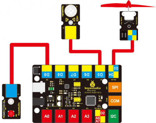
Project 7: Fire extinguishing
Overview How to blow out the fire? You might be able to use this fan module to add flavor to your own interesting projects.
Component Required
EASY plug control board*1
EASY plug Fan Motor Module*1
RJ11 cable*1
USB cable*1
Component Introduction
EASY plug Fan Motor Module
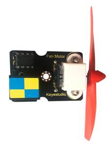
The fan motor module uses the L9110 driver to control the forward and reverse rotation of propeller, which can easily blow out the fire of a lighter 20cm away. It should be connected to the double digital port with only one line, pretty convenient. Make an air aerial propeller vessel, a cooling system, or spinning machine with this small fan module. Add flavor to your own interesting projects with this module. This module is commonly used for STEM class.
Fan diameter: 75mm
Interface: double digital
Working voltage: 5V
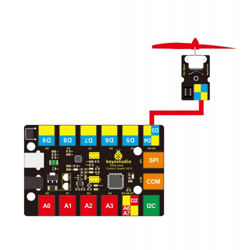
Connect It Up Connect the EASY Plug fan motor module to control board using an RJ11 cable.
Upload the Code
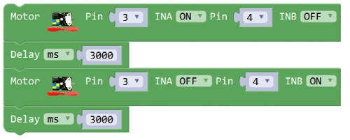
What You Should See Done uploading the code, the motor fan will rotate forward for 3 seconds, and then rotate reverse for 3 seconds, repeatedly.
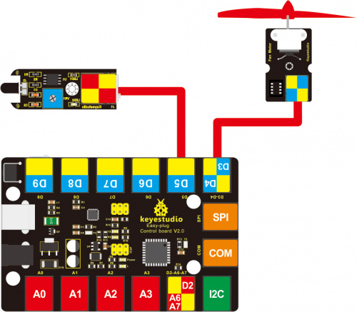
Project 8: There’s flame
Overview What's the simplest way to check the fire happened? Use a flame sensor. In this project, we simply test the flame sensor to turn on led if detecting flame.
Component Required
EASY plug control board*1
EASY plug Flame Sensor *1
EASY plug LED Module*1
EASY plug Fan Motor*1
RJ11 cable *2
USB cable*1
Component Introduction
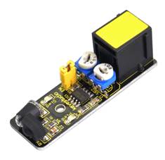
EASY plug Flame Sensor Module
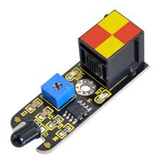
The flame sensor can be used to detect fire or other wavelength at 760nm ~1100nm light. In the fire-fighting robot game, the flame plays an important role in the probe, which can be used as the robot's eyes to find fire source. The potentiometer on the flame sensor can be used to adjust the sensitivity.
Supply Voltage: 3.3V to 5V
Detection range: 500px (4.8V) ~ 2500px (1V)
Spectral Bandwidth Range: 760nm ~ 1100nm
Operating temperature: -25℃ to 85℃
Sensor type: digital
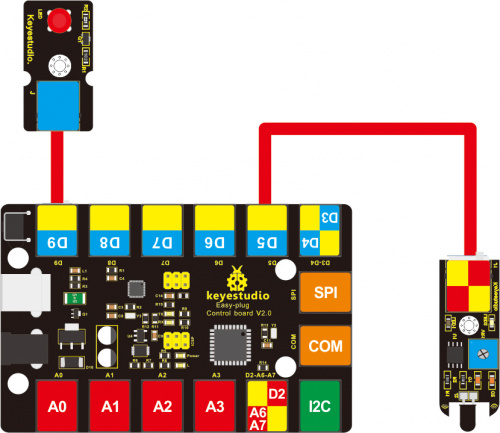
Connect It Up Connect the EASY Plug Flame Sensor and LED module to control board using RJ11 cables.
Upload the Code
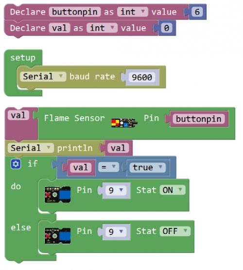
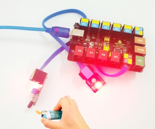
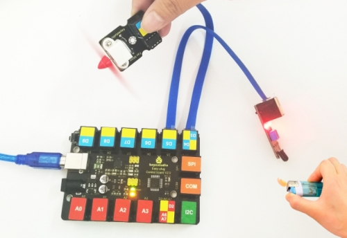
What You Should See Done uploading the code, put a lighter close to the flame sensor. Once the sensor detects the flame, the led lights up. If isn’t, you are able to adjust the sensitivity by a potentiometer.
Little Knowledge:
You are able to adjust the sensitivity by a blue potentiometer on the sensor.
EASY plug Flame Sensor Module
Simulating Fire Extinguisher
Let’s go into an interesting project. When detecting the flame by flame sensor, the fan motor will rotate to blow out the fire. Hookup Guide
Test Code
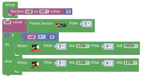
What You Should See Done uploading the code, put a lighter close to the flame sensor. Once the sensor detects the flame, you should see the fan motor run.
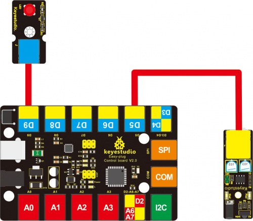
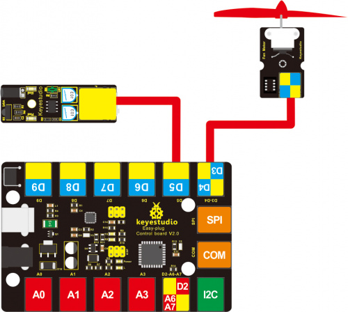
Project 9: Avoiding obstacles
Overview Why some intelligent robots can automatically avoid an obstacle ahead? Easily, use an obstacle avoidance sensor. In this project, we’ll simply test the obstacle avoidance sensor.
Component Required
EASY plug control board*1
EASY plug obstacle detector sensor *1
EASY plug LED module *1
EASY plug motor *1
RJ11 cable *2
USB cable*1
Component Introduction
EASY plug Obstacle Avoidance Sensor
Infrared obstacle avoidance sensor is equipped with distance adjustment function and is especially designed for wheeled robots. This sensor has strong adaptability to ambient light and is of high precision. It has a pair of infrared transmitting and receiving tube. When infrared ray launched by the transmitting tube encounters an obstacle (its reflector), the infrared ray is reflected to the receiving tube, after a comparator circuit processing, the indicator will light up. You can adjust the detection distance by rotating the potentiometer knob, the effective distance range of 2~40cm. They can be widely used in robot obstacle avoidance, avoidance car, line count, and black and white line tracking and many other occasions.
Working voltage: DC 3.3V-5V
Working current: ≥20mA
Working temperature: -10℃ to+50℃
Detection distance: 2~40cm
Output signal: TTL voltage
Effective Angle: 35°
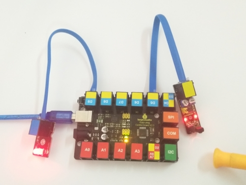
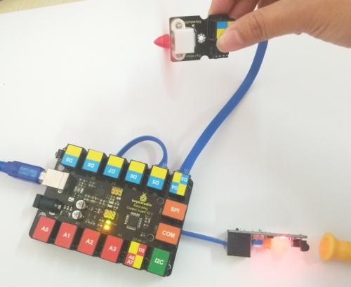
Connect It Up Connect the EASY Plug obstacle detector sensor and LED module to control board using RJ11 cables.
Test Code
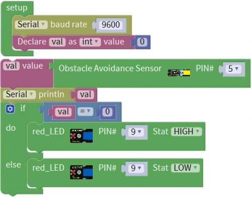
What You Should See
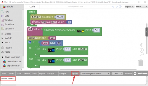
Done uploading the code, when the sensor detects an obstacle, the led is turned on.
Controlling Motor
In the previous section, we use the obstacle detector sensor to control the LED on and off. Now, let’s try another play, controlling the motor rotating. Hookup Guide
Test Code
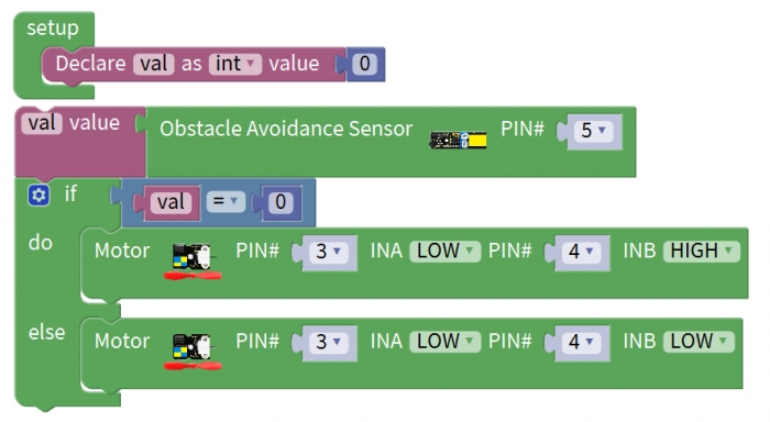
What You Should See Done uploading the code, when the sensor detects an obstacle, the fan motor rotates. Otherwise, fan motor stops.
Troubleshooting:
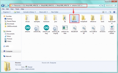
Compiling Fails ?
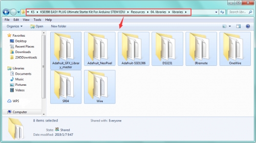
This happens sometimes, the most likely case is a library file not added. You should be sure that all the libraries are added to the libraries directory of Arduino-1.8.5. Shown below.

Program Not Uploading?
This happens sometimes, the most likely case is a confused Board and serial port, you should firstly select your proper board and port.
Project 10: Servo
Overview This lesson we are going to rotate the servo motor.
Component Required
EASY plug control board*1
EASY plug Servo Module *1
OpenELAB Micro Servo *1
RJ11 cable *1
USB cable*1
Component Introduction If you want to use the Micro Servo and EASY PLUG control board to do some experiments, you need to use the EASY plug Servo extension module. The EASY plug Servo module is extended into Registered Jack, so you can connect it to EASY PLUG control board using only a RJ11 cable. The Servo module also comes with 3pins of 2.54mm pin pitch, fully compatible with servo pins.
EASY plug Servo Module +Micro Servo
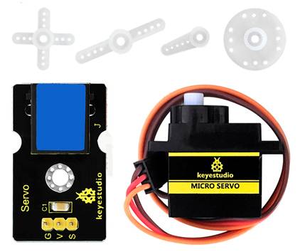
Servo motor comes with many specifications. But all of them have three connection wires, distinguished by brown, red, orange colors. Brown one is for ground, red one for power positive, orange one for signal line. Included with your Micro Servo you will find a variety of white motor mounts that connect to the shaft of your servo. You may choose to attach any mount you wish for the circuit. It will serve as a visual aid, making it easier to see the servo spin.
The rotation angle of servo is controlled by regulating the duty cycle of the PWM(Pulse-Width Modulation) signal. The standard cycle of the PWM signal is fixed at 20ms (50 Hz), and the pulse width is distributed between 1ms-2ms. The pulse width corresponds to the rotation angle ( 0°~90°) of servo.

Micro Servo Parameters
Operating voltage: DC 4.8V〜6V
Angle range: about 90°(in 1000→2000μsec)
Pulsewidth range: 1000→2000μsec
No-load speed: 0.12±0.01 sec/60(DC 4.8V); 0.1±0.01 sec/60(DC 6V)
No-load current: 200±20mA(DC 4.8V); 220±20mA(DC 6V)
Stop torque: 1.1±0.01kg/cm(DC 4.8V); 1.3±0.1kg/cm(DC 6V)
Stop current: 600±30mA(DC 4.8V); 750±30mA(DC 6V)
Standby current: 4±1mA(DC 4.8V); 4±1mA(DC 6V)
Operation temperature: -10℃〜50℃
Save temperature: -20℃〜60℃
Motor wire length: 250 ± 5 mm
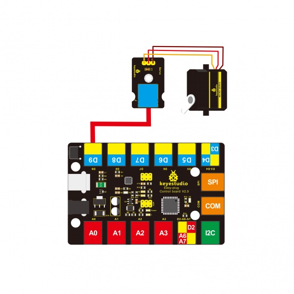
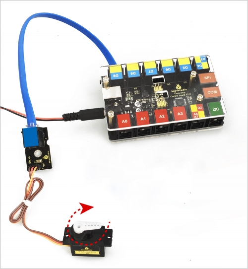
Connect It Up Connect the servo motor to EASY Plug Servo module. Brown line is for ground, red one for V pin, orange one for signal pin. Then connect them to control board using an RJ11 cable.
Upload the Code
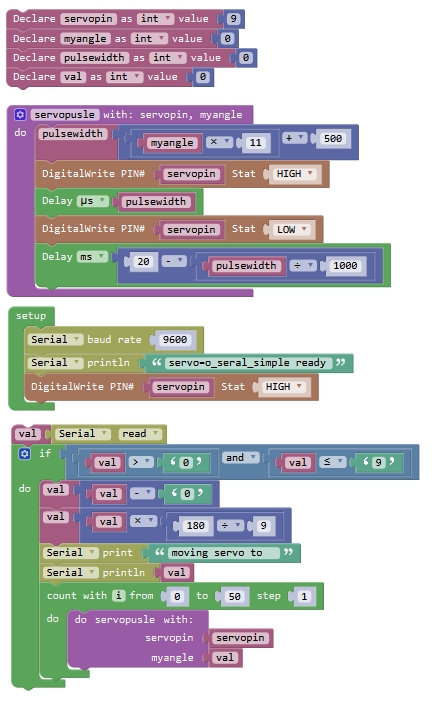
What You Should See
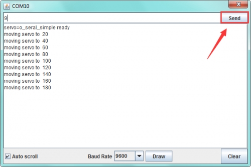
After uploading the code, open the serial monitor, enter the number 1 to 9, and click Send, it will control the servo motor rotate at a certain angle.
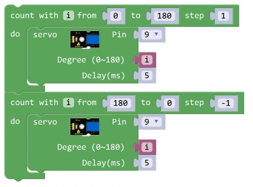
Rotating back and forth
Complete the above project, you can also upload the code below to control the servo motor rotating back and forth at a certain angle. Test Code
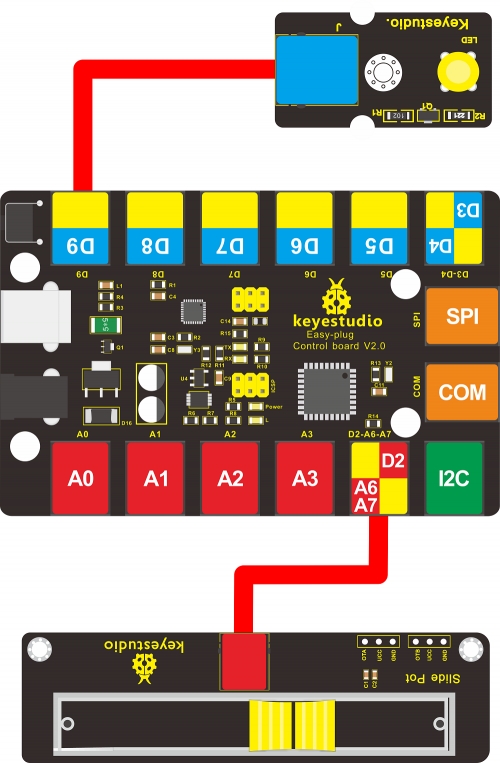
Project 11: Slide Position
Overview This lesson you will learn how to use slide potentiometer to control the LED brightness and servo rotation.
Component Required
EASY plug control board*1
EASY plug slide potentiometer *1
EASY plug LED module*1
Servo motor *1
RJ11 cable*2
USB cable*1
EASY plug Slide Potentiometer
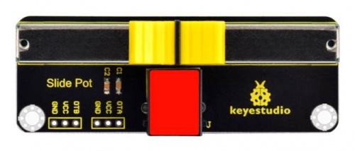
Component Introduction The EASY plug slide potentiometer uses high quality sliding appliances for stable and reliable performance. It is a dual analog output that outputs a 0-VCC analog voltage signal. The module pins are extended into Registered jack, so you can easily connect it to EASY Plug control board using a RJ11 cable. There are 6 pad interfaces on the module. So you can solder two 3pin headers with a pitch of 2.54mm on the module. It can be used to connect with other MCUs. The signal terminal outputs two analog values. The sum of the two analog values is 1023.
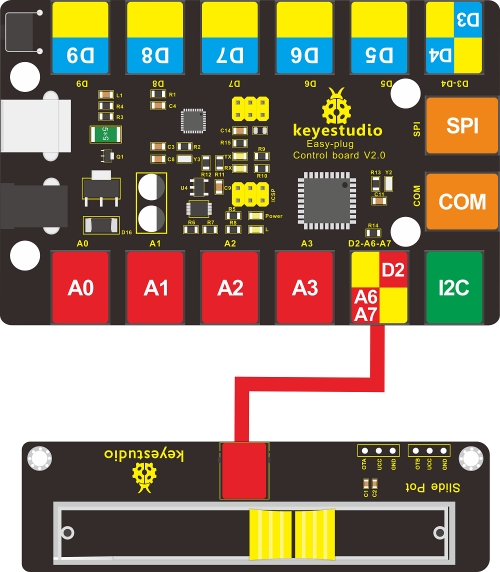
Connect It Up Connect the EASY Plug Slide Potentiometer module to control board using an RJ11 cable.
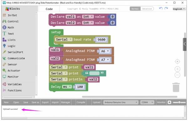
Upload the Code
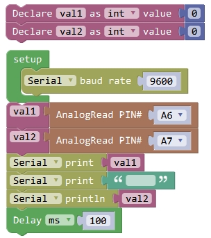
What You Should See After uploading the code, open the serial monitor and set the baud rate to 9600; you should be able to see the analog value of analog pin A6,A7. If slide the slider, the value will change.

Controlling LED Brightness
Except from reading the analog value of slide potentiometer, you are able to use the slide potentiometer to control the brightness of LED. Hookup Guide
Test Code
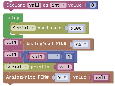
What You Should See After uploading the code, slide the potentiometer, the brightness of LED will change.
Controlling Servo Angle
Hookup Guide
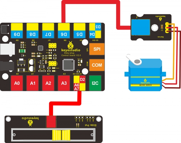
Test Code
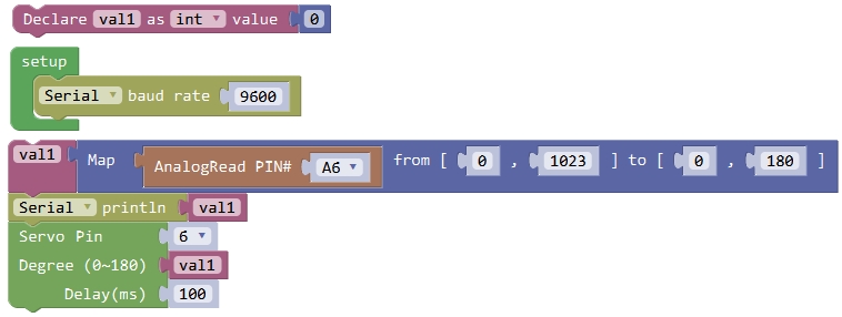
What You Should See After uploading the code, slide the potentiometer, the servo motor will rotate to a certain angle.
Project 12: RGB
Overview This lesson we are going to show you shiny light color. Component Required
EASY plug control board*1
EASY plug RGB module *1
RJ11 cable*1
USB cable*1
Component Introduction
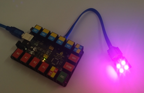
EASY plug 2812 2x2 full-color RGB Module
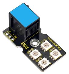
EASY plug 2812 2x2 full color RGB module is a smart external control LED light source that integrates control circuit and lighting circuit. Each LED has the same appearance as a 5050 LED bead, and each component is a pixel point. The pixel point includes an intelligent digital interface data latch signal shaping and amplifying driving circuit, as well as a high-precision internal oscillator and a 12V high-voltage programmable constant current control part, which effectively ensures that the color of the pixel point light is highly uniform. The data protocol adopts the single-line return-to-zero code communication mode. After power-on and reset the pixel point, the S pin receives the data transmitted from the controller. And the 24-bit data are extracted by the first pixel and then sent to the data latch inside the pixel point. LED has advantages of low voltage drive, environmental protection and energy saving, high brightness, wide scattering angle, good consistency, ultra low power, long life and so on.
Specifications
Operating Voltage: DC5V
Power: 0.1W
Light Source: SMD 5050 RGB
IC model: 4 / WS2811
Gray level: 256 levels
Illumination angle: 180°
Luminous color: can be adjusted by the controller, white, red, yellow, blue, green, etc.
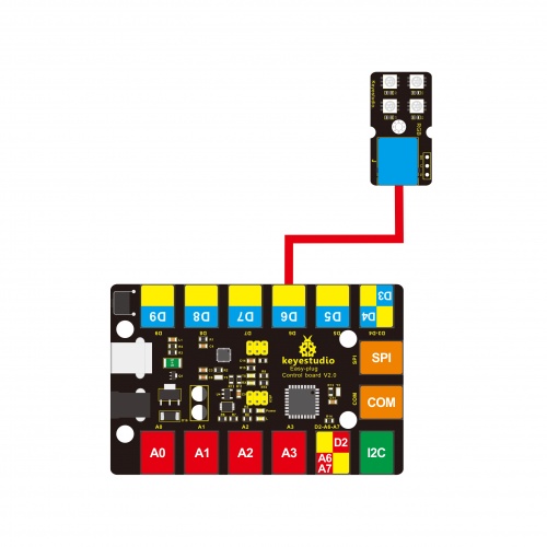
Connect It Up
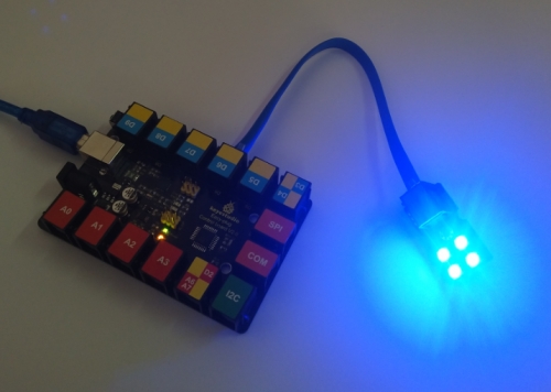
Upload the Code
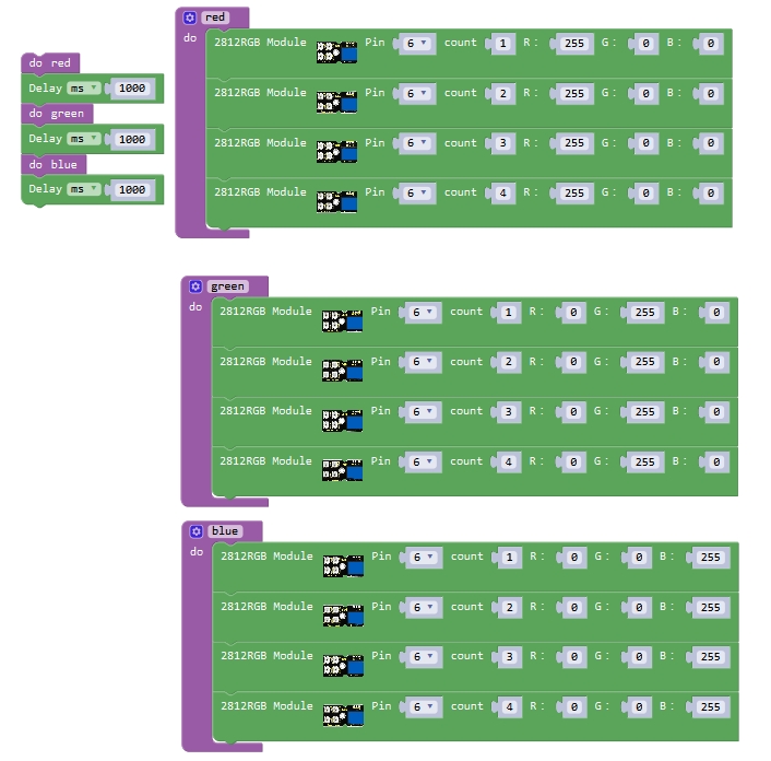
What You Should See After uploading the code, you should see the 4 RGB LEDs flashing in red, green, and blue,circularly.
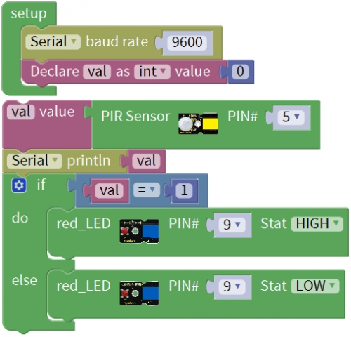
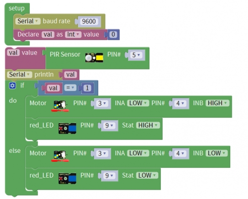
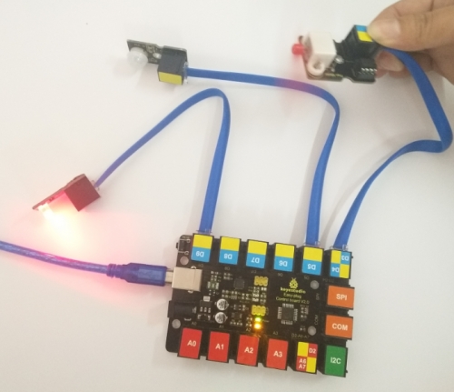
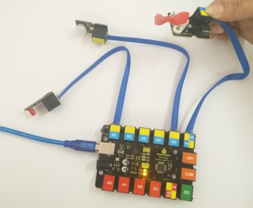
Project 13: Someone is in this area!
Overview How can we know someone enters and leaves a certain area? Great, use a PIR motion sensor. The PIR sensor allows to detect motion.That information can be useful, for example, to trigger an alarm or to turn on the lights.
Component Required
EASY plug control board*1
EASY plug PIR Motion Sensor*1
EASY plug LED module*1
EASY plug Fan motor*1
RJ11 cable*3
USB cable*1
Component Introduction
EASY plug Flame Sensor Module
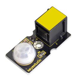
PIR stands for Pyroelectric Infrared (many times, they are also referred as Passive Infrared sensors). This is because their principle of operation is based on the detection of infrared energy emitted by a moving body. The PIR sensor can detect infrared signals from a moving person or moving animal, outputting switching signals. One important thing to mention is that when motion is detected, the output will stay high for 2.3 to 3 seconds after the motion stops. Regarding the power supply, it can work with voltages of both 3.3V and 5V. The device has a detection range of 7 meters and a detection angle of 100º.
Input Voltage: 3.3 ~ 5V, Maximum 6V
Working Current: 15uA
Working Temperature: -20 ~ 85℃
Output Voltage: High 3V, Low 0V
Output Delay Time (High Level): About 2.3 to 3 Seconds
Detection angle: 100°
Detection distance: 7 meters
Pin limit current: 100mA
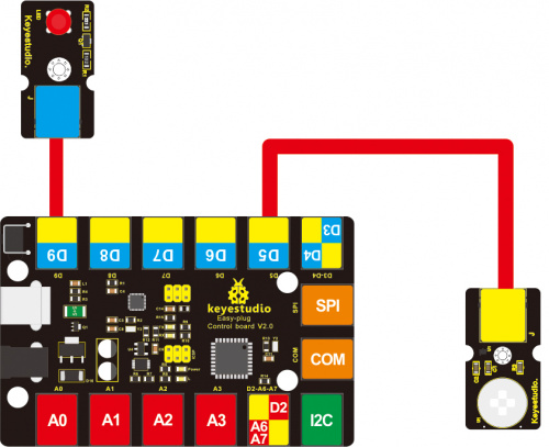
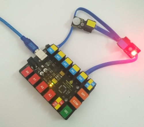
Connect It Up Connect the EASY Plug PIR Motion sensor and LED module to control board using RJ11 cables.
Test Code
What You Should See After uploading the code, slide the potentiometer, the servo motor will rotate to a certain angle.
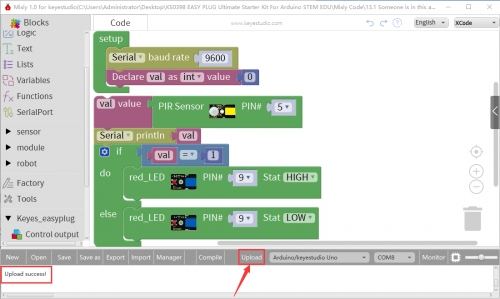
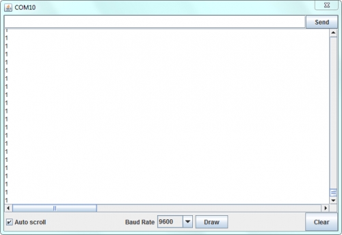
Done uploading the code, if the sensor detects someone moving nearby, you should see the LED is turned on.
Open the serial monitor and set the baud rate to 9600, it will print out the data.
Controlling Fan Motor
Hookup Guide
Test Code
What You Should See If the sensor detects someone moving nearby, you should see the LED is turned on, and the fan motor is rotating. Otherwise, LED is turned off and motor stops rotating.
Project 14: Joystick
Overview Lots of robot projects need joystick. This joystick module provides an affordable solution. In the following, we are going to test the joystick.
Component Required
EASY plug control board*1
EASY plug Joystick Module *1
EASY plug LED module *3
RJ11 cable *4
USB cable*1
Component Introduction
EASY plug Joystick Module
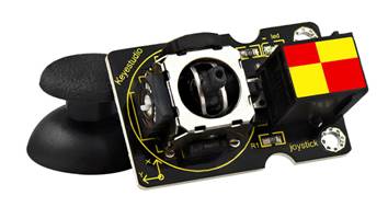
Lots of robot projects need joystick. This module provides an affordable solution. By simply connecting to two analog inputs, the robot is at your commands with X, Y control. It also has a switch that is connected to a digital pin. This joystick module can be easily connect to EASY PLUG control board with only one cable.
Interface: Easy plug
Supply Voltage: 3.3V to 5V
Interface: Digital
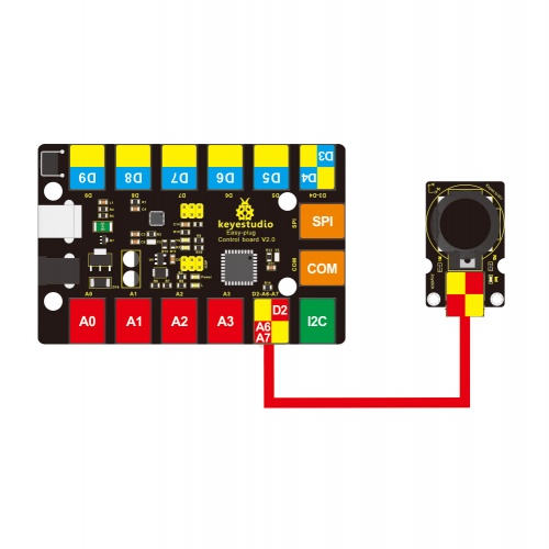
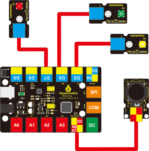
Connect It Up Connect the EASY Plug Joystick module to control board using an RJ11 cable. Note: X-axis is connected to A6, Y-axis is connected to A7, Z-axis is default by D2
Upload the Code
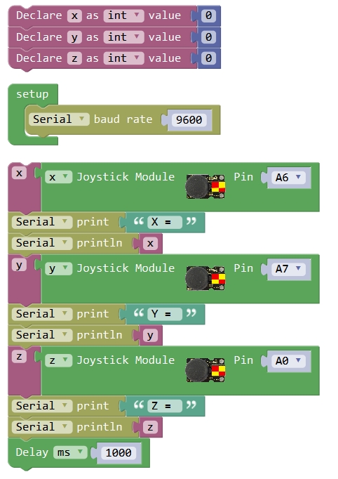
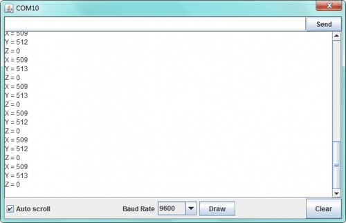
What You Should See
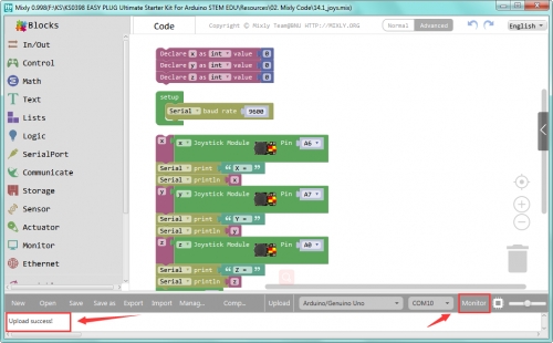
Done uploading the code, open the serial monitor and set the baud rate to 9600. If push the Joystick button towards different direction, you should get the different value.
Controlling LED Lights
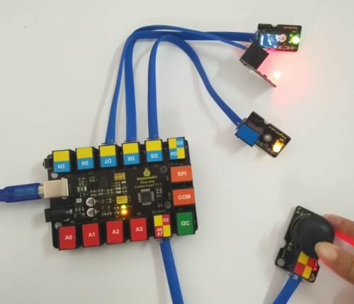
Hookup Guide
Test Code
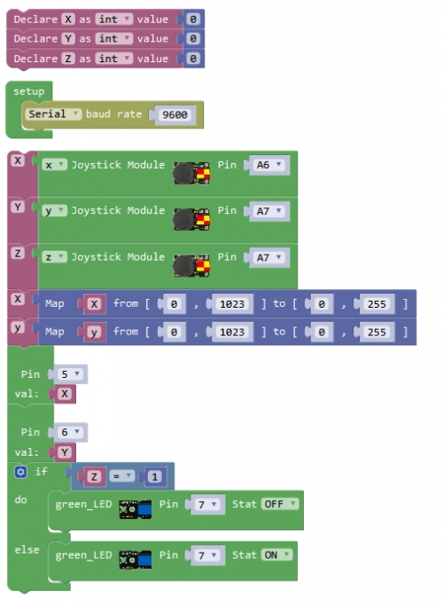
What You Should See Upload the code successfully, push the Joystick X-axis to downward, the LED light connected to D5 will become off. If push the Joystick Y-axis to leftward, the LED light connected to D6 will be turned off. Z-axis will control the LED light connected to D7.
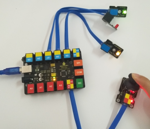
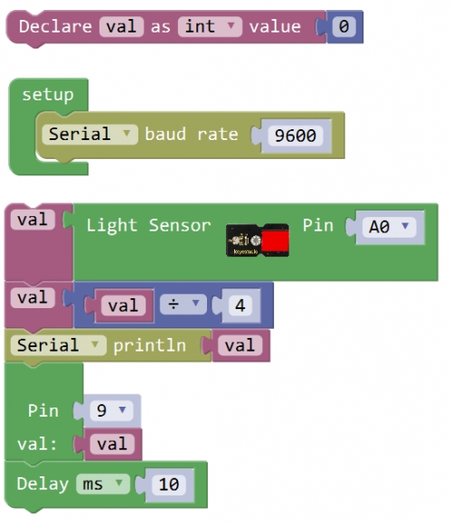
Project 15: Ambient Light
Overview This project we will test the ambient light. You can use analog reading to read the data from this sensor. Component Required
EASY plug control board*1
EASY plug TEMT6000 Light Sensor *1
EASY plug LED module *1
EASY plug RGB module *1
RJ11 cable *2
USB cable*1
Component Introduction
EASY plug TEMT6000 Ambient Light Sensor
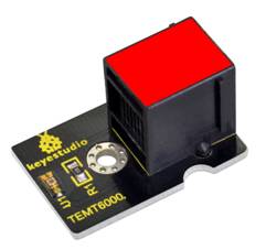
Light sensors are probably one of the most common sensors in life. They can be found in your laptop, phone or home lighting system. A light sensor measures the level of light in a room or ambient light in a space. This EASY plug TEMT6000 light sensor uses a special ambient light detector (TEMT6000) with spectral response that closely emulates the human eye. It does react well to very small changes in a wide range of brightness, however, it does not react well to IR or UV light. The sensor can help you to to detect the light density.
Supply Voltage: +5V DC 50mA
Interface:Analog Input
Near Human Eye Spectral Response and Very Low IR Sensitivity
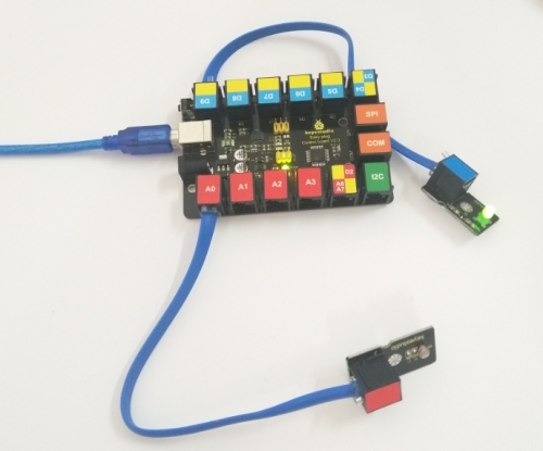
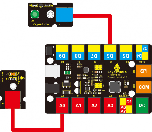
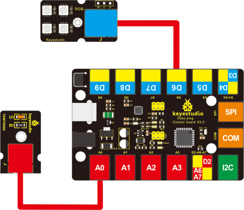
Connect It Up Connect the EASY Plug TEMT6000 sensor to control board using an RJ11 cable.
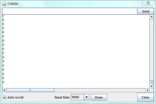
Upload the Code
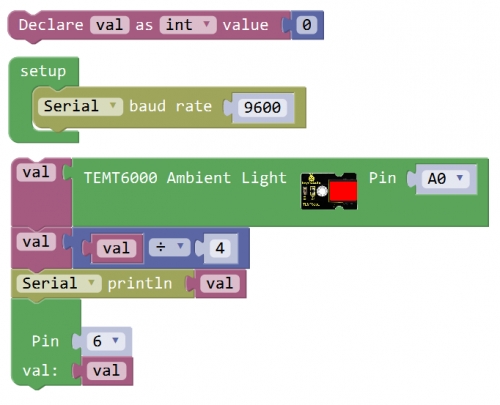
What You Should See
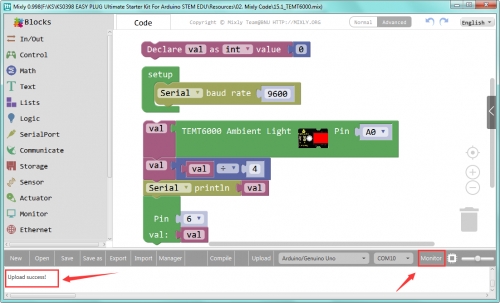
Done uploading the code, open the serial monitor and set the baud rate to 9600, you should be able to see the printed analog value. When the sensor detects different light intensity, the brightness of LED will change.
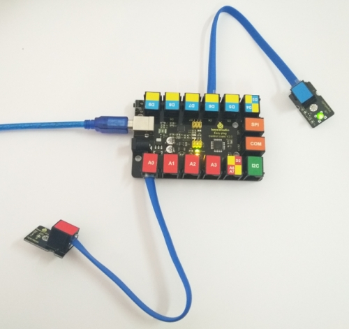
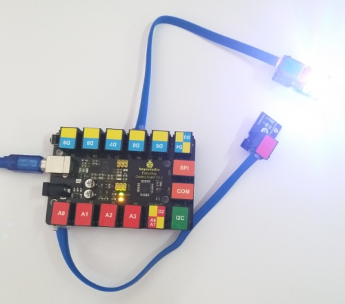
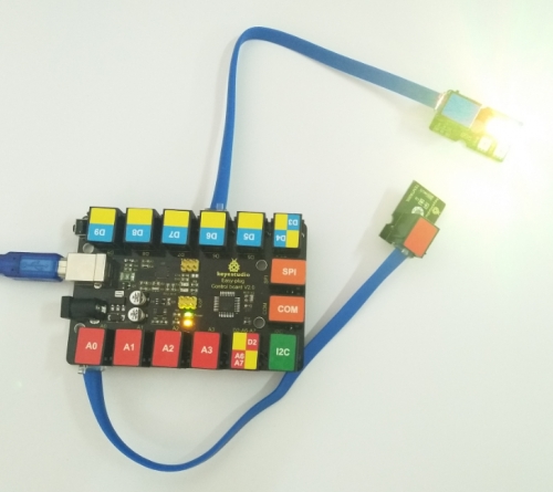
Controlling RGB Flash
Hookup Guide
Test Code
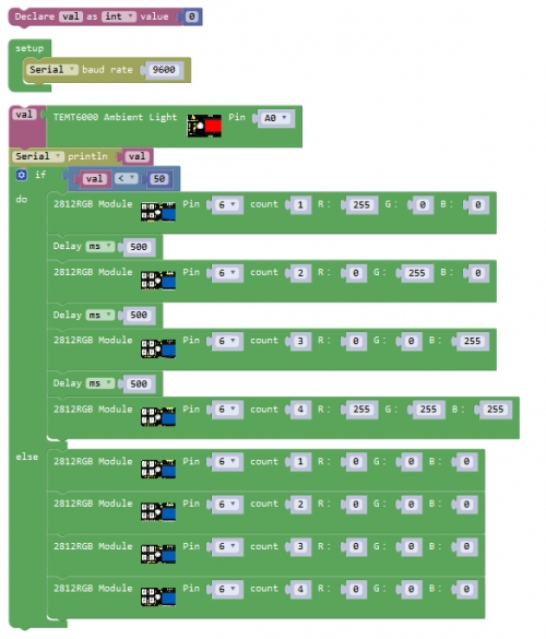
What You Should See Upload the code successfully, when the measured light intensity is less than 50, RGB lights are turned on. Light 1 flashes in red, light 2 flashes in green, light 3 flashes in blue, light 4 flashes in white, with a delay time 500ms.
Project 16: Hello, kaka!
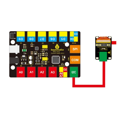
Overview An OLED (organic light-emitting diode) can be widely used in mobile devices for display applications. In the project, we will show you how to use an OLED module to display the text.
Component Required
EASY plug control board*1
EASY plug OLED Module*1
RJ11 cable*1
USB cable*1
Component Introduction
EASY plug OLED Module
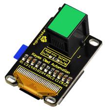
OLED is short for organic light emitting diode. On the microscopic level, an OLED display is a matrix of organic LEDs that light up when they emit energy. Our EASY Plug OLED displays are perfect when you need a small display with vivid, high-contrast color. The visible portion of the OLED measures 0.96" diagonal and contains 128 x 64 pixels. An OLED display works without a backlight. Thus, it can display deep black levels and can be thinner and lighter than a liquid crystal display (LCD). In low ambient light conditions such as a dark room an OLED screen can achieve a higher contrast ratio than an LCD. OLED technology is used in commercial applications such as displays for mobile phones and portable digital media players, car radios and digital cameras among others.
Specifications
0.96" diagonal OLED
Pixels: 128 × 64
Color Depth: Monochrome(White)
5V power
Brightness (cd/m2): 100(Typ)
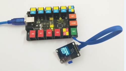
Connect It Up Connect the EASY Plug OLED module to control board using an RJ11 cable.
Upload the Code
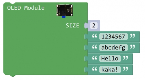
What You Should See
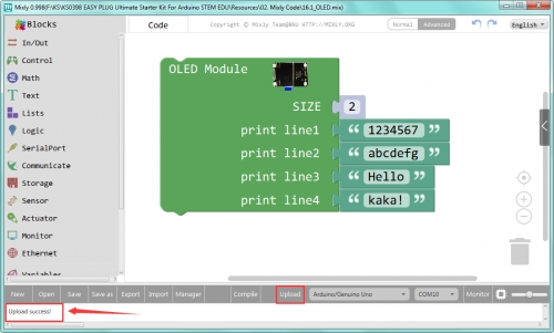
Done uploading the code, you should be able to see the text is displayed on the OLED screen.
Troubleshooting:
Upload Failed ?
This happens sometimes, the most likely case is a confused Board and serial port, you should firstly select your proper board and port. Or make sure you have placed all the libraries below into arduino-1.8.5 libraries folder directory. Pay more attention that the library folder can’t be overlapped.
Project 17: I’m thirsty
Overview This lesson we are going to use the soil sensor to detect the soil moisture of your plant.
Component Required
EASY plug control board*1
EASY plug soil moisture sensor*1
EASY plug OLED module*1
RJ11 cable * 2
USB cable*1
Component Introduction
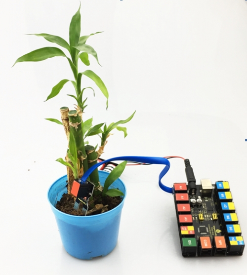
OpenELAB EASY plug Soil Moisture Sensor
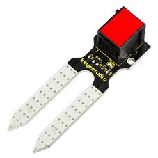
The EASY Plug soil moisture sensor can read the amount of moisture present in the soil surrounding it. It's an ideal for monitoring an urban garden, or your pet plant's water level. This soil moisture sensor uses the two probes to pass current through the soil, and then it reads that resistance to get the moisture level. More water makes the soil conduct electricity more easily (less resistance), while dry soil conducts electricity poorly (more resistance). If you use this sensor to make an automatic watering device, it will be helpful to remind you to water your indoor plants or to monitor the soil moisture in your garden.
Connector: Easy plug
Power Supply: 3.3V or 5V
Working Current: ≤ 20mA
Output Voltage: 0-2.3V
Sensor type: Analog output
Surface finish: immersion tin
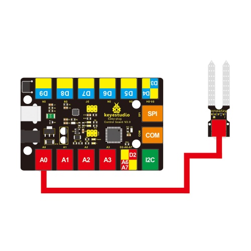
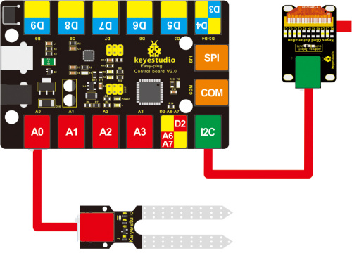
Connect It Up Connect the EASY Plug soil sensor to control board using an RJ11 cable.
Upload the Code
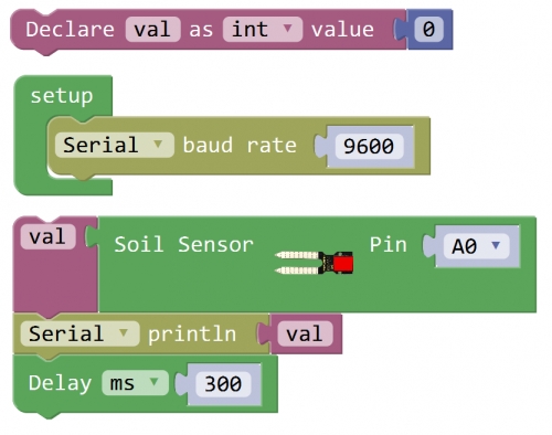
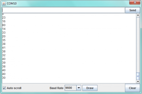
What You Should See
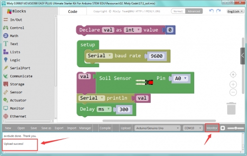
Done uploading the code, open the serial monitor and set the baud rate to 9600, you can see the analog value is 0. When place the two probes of moisture sensor into your plant soil, you can see the value change.
Adding OLED Display
If you want to display the soil moisture value more convenient, you can add OLED screen.
Hookup Guide
Test Code
What You Should See Upload success, you should see the soil value is showed on the OLED screen.
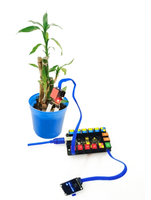
Project 18: Is there gas leakage?
Overview This project we will test the gas sensor. You can use analog reading to read the data from this sensor. Component Required
EASY plug control board*1
EASY plug Analog Gas Sensor *1
EASY plug OLED module*1
RJ11 cable*2
USB cable*1
Component Introduction
EASY plug Analog Gas Sensor
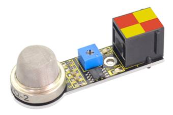
This analog gas sensor - MQ2 is used in gas leakage detecting equipment in consumer electronics and industrial markets. This sensor is suitable for detecting LPG, I-butane, propane, methane, alcohol, Hydrogen and smoke. It has high sensitivity and quick response. In addition, the sensitivity can be adjusted by the potentiometer.
Interface: Easy plug
Power supply: 5V
Interface type: Digital and Analog
Wide detecting scope
Simple drive circuit
Stable and long lifespan
Quick response and High sensitivity
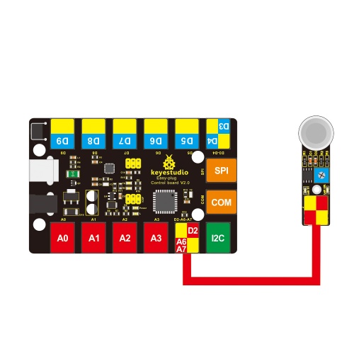
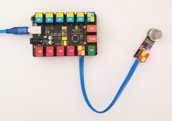
Connect It Up Connect the EASY Plug analog gas sensor to control board using an RJ11 cable.
Upload the Code
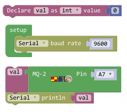
What You Should See
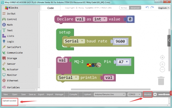
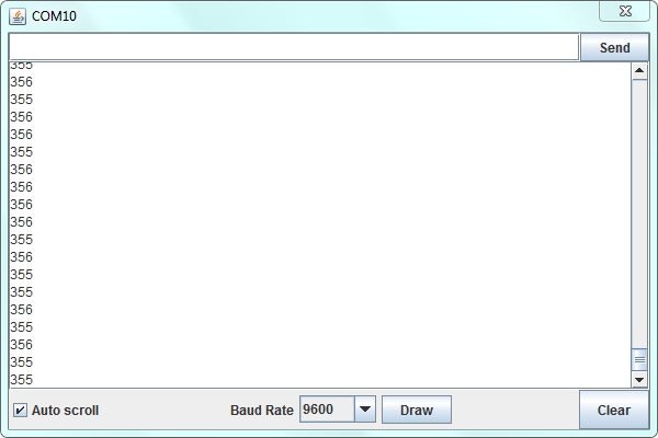
Done uploading the test code, open the serial monitor and set the baud rate to 9600, you should be able to see the analog value.
Adding OLED Display
If you want to display the gas analog value more convenient, you can add OLED screen.
Hookup Guide
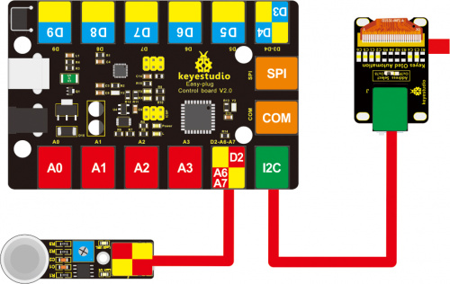
Test Code
What You Should See Upload success, you should be able to see the analog value is showed on the OLED screen.
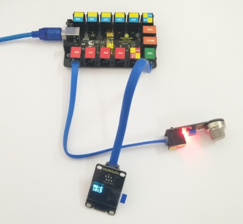
Project 19: Ultrasonic ranging
Overview The distance sensors are really commonly seen in robotics projects. So in this project we will measure the distance with an ultrasound sensor.
Component Required
EASY plug control board*1
EASY plug SR01 Ultrasonic *1
EASY plug LED module *1
RJ11 cable *2
USB cable *1
Component Introduction
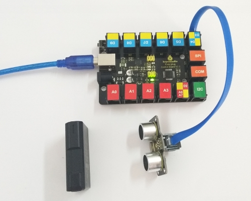
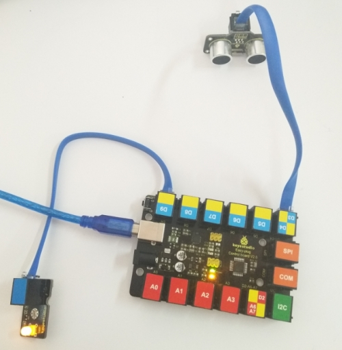
EASY plug SR01 Ultrasonic Module
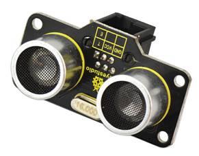
This EASY Plug SR01 Ultrasonic module includes ultrasonic transmitter, receiver and corresponding control circuit. It should be connected to the double digital interface with only one line, which is very convenient. The distance sensor are really common in robotics projects, very useful for automation, interactive art and motion sensing. The module comes with four fixed holes, so that can easily fix it on other devices, such as the servo plastic platform and so on.
Operating Voltage: DC 5V
Operating Current: 15mA
Operating Frequency: 40KHz
Max Range: 3--5m
Min Range: 2cm
Measuring Angle: 15 degree
Trigger Input Signal: 10µS TTL pulse
Interface:double digital
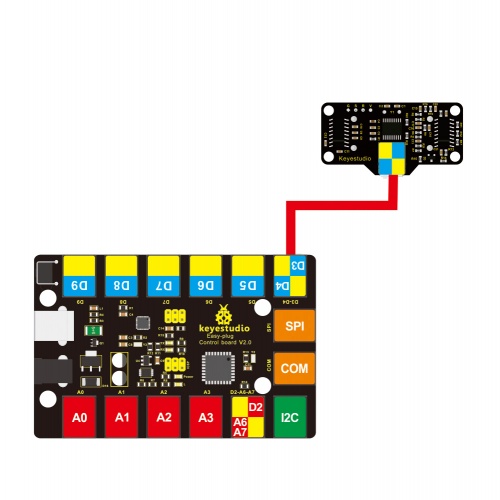
Connect It Up Connect the EASY Plug Ultrasonic module to control board using an RJ11 cable.
Upload the Code
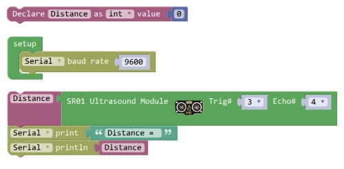
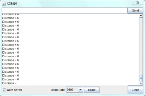
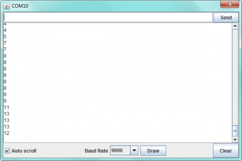
What You Should See Done uploading the code, open the serial monitor and set the baud rate to 9600. You should see the measured distance between the ultrasonic sensor and front obstacle.
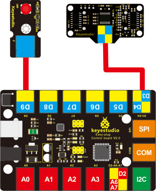
Turn on Light
When the measured distance between an obstacle and ultrasonic sensor is less than a certain range, turn the led on. Hookup Guide
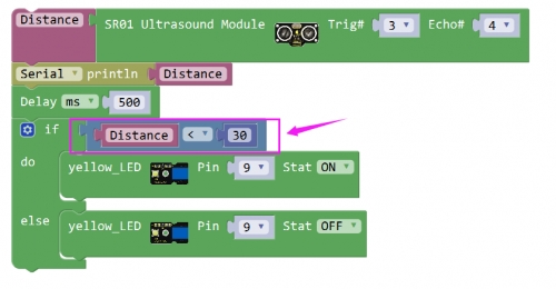
Test Code
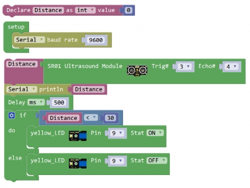
What You Should See Upload success, when the measured distance is less than 30, the LED will be turned on. Otherwise, the LED is turned off.
Little Knowledge:
You can modify the setting distance in the code here, so that turn on or off led according to the obstacle distance measured by ultrasonic sensor.
Project 20: What’s the temperature
Overview In this project, you will learn how to use the temperature sensor with your EASY Plug control board, and display the analog temperature value on the serial monitor.
Component Required
EASY plug control board*1
EASY plug DS18B20 Sensor *1
EASY plug OLED Module*1
RJ11 cable *2
USB cable*1
Component Introduction
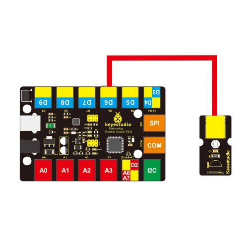
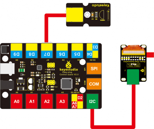
EASY plug DS18B20 Temperature Sensor
The DS18B20 temperature sensor is exactly what it sounds like - a sensor used to measure ambient temperature. The usable temperature ranges from -55°C to +125°C. It also supports multi-point mesh networking. While there are many types of temperature sensors available in the market, the DS18B20 temperature sensor is the best choice in applications which require high accuracy and high reliability. For electronic enthusiasts and hobbyists, the DS18B20 is a good start for learning and developing temperature-dependent prototypes.
Supply Voltage: 3.3V to 5V
Temperature range: -55°C to +125°C
Interface: Digital
Connect It Up Connect the EASY Plug DS18B20 temperature sensor to control board using an RJ11 cable.
Upload the Code
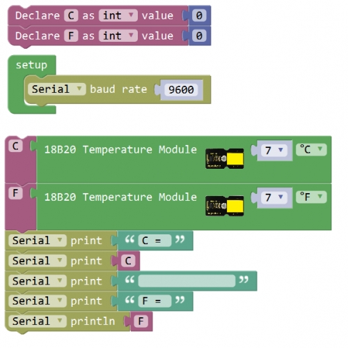
What You Should See
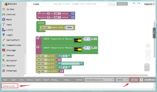
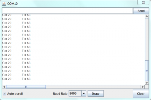
Done uploading the code, open the serial monitor, on the window will print out the Celsius and Fahrenheit value.
OLED Display
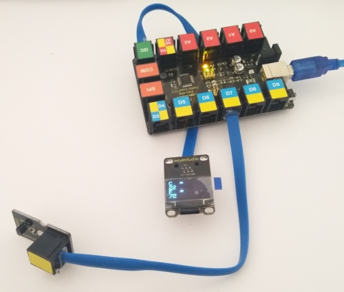
Hookup Guide
Test Code
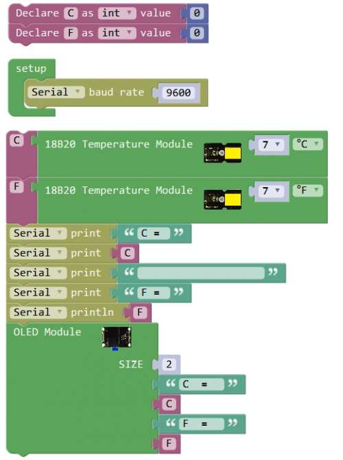
What You Should See Upload success, you should be able to see the Celsius and Fahrenheit value are printed out on the OLED screen.
Troubleshooting:
OLED Not Lighting Up?
If upload the code successfully, but LED still not lights up. Make sure your board and OLED module are connected correctly.
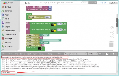
Upload Failed ?
This happens sometimes, the most likely case is a confused Board and serial port, you should firstly select your proper board and port. Or check whether add the library or not.
Project 21: What time is it?
Overview In this project, we will show you how to display the time and date.
Component Required
EASY plug control board*1
EASY plug DS3231 Clock Module*1
RJ11 cable*1
USB cable*1
Component Introduction
EASY plug DS3231 Clock Module
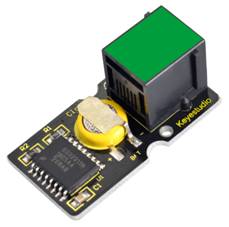
The DS3231 is a low-cost, extremely accurate I2C real-time clock (RTC) with an integrated temperature-compensated crystal oscillator (TCXO) and crystal. A real-time clock (RTC) is a computer clock (most often in the form of an integrated circuit) that keeps track of the current time. It integrated with a battery input, which can maintain accurate timekeeping when power off. The integrated crystal resonator ensures the accuracy of clock. So this RTC solution should be worth to try.
Temperature range: -40℃ to +85℃
Timing accuracy: about ± 5ppm
Output: 1Hz and 32.768kHz
High speed (400kHz), I2C serial bus
Supply voltage: 3.3V to 5.5V
Output Level: TTL level
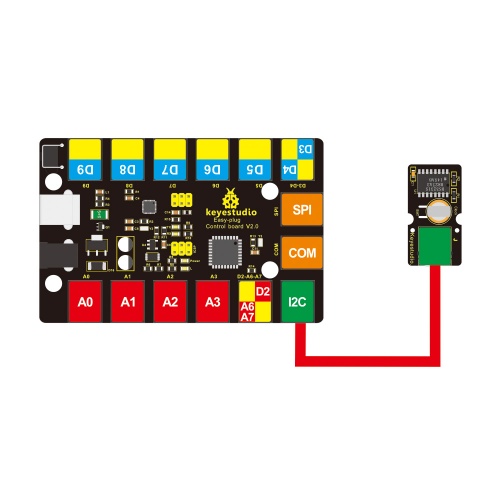
Connect It Up
Upload the Code
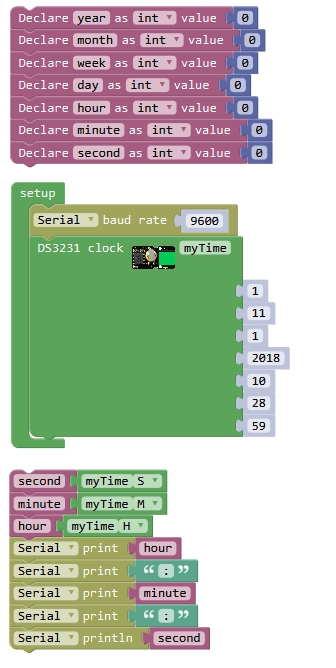
What You Should See
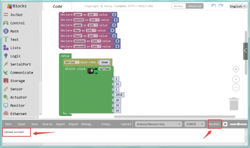
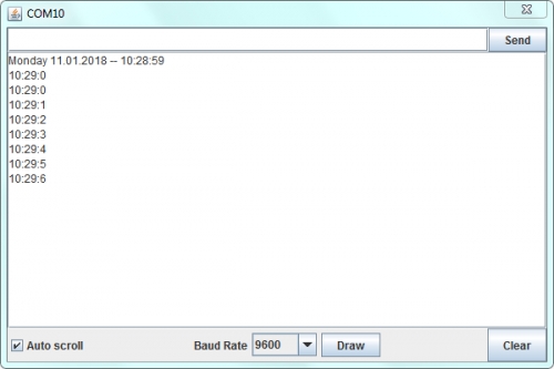
Done uploading the code, open the serial monitor and set the baud rate to 9600, you should be able to see the date and the time.
Project 22: I receive a signal
Overview Infrared devices are widely used, and often for remote controlled devices. With this IR receiver, your program project is now able to receive command from any IR remote controller. Next, let’s do a simple test. Component Required
EASY plug control board*1
EASY plug IR Receiver Module *1
EASY plug LED Module *1
RJ11 cable*2
USB cable*1
Component Introduction
EASY plug IR Receiver Module
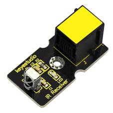
Infrared receiver is a component with functions of reception, amplification, and demodulation. The internal IC has already been demodulated so that can directly output digital signal. Well, it will be also easy to make your own IR controller using IR transmitter.
Socket: Easy plug
Power Supply: 5V
Interface:Digital
Modulate Frequency: 38Khz
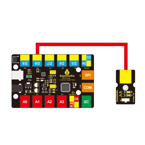
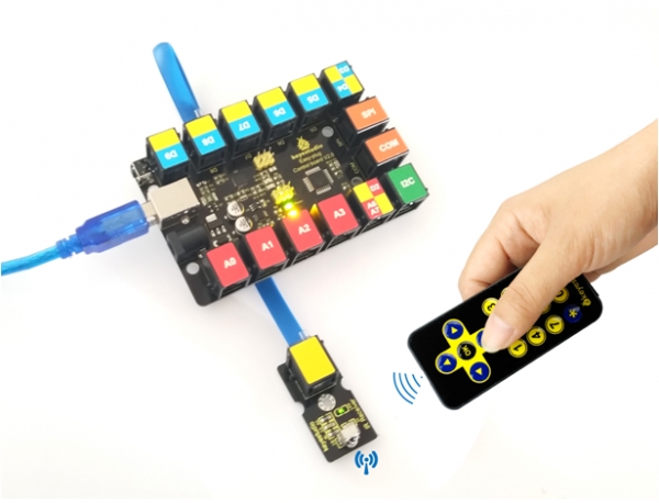
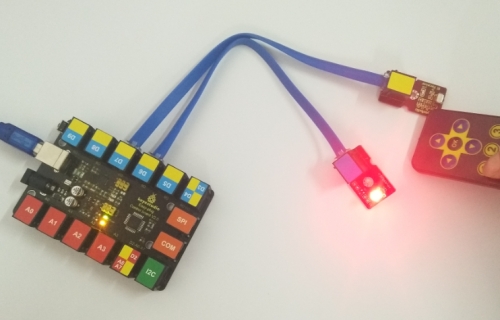
Connect It Up Connect the EASY Plug Infrared receiver module to control board using an RJ11 cable.
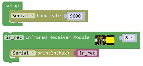
Upload the Code
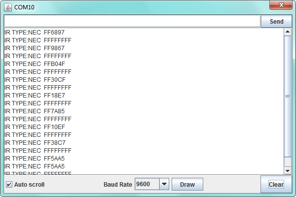
What You Should See
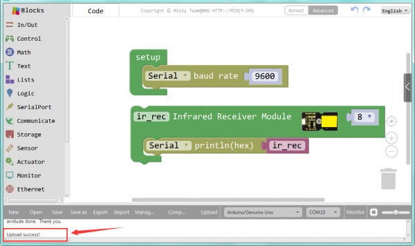
Done uploading the code, when aiming at the IR receiver, press down the key on an IR remote controller, you should see the key decoding is displayed on the serial monitor. If long press the key, it will appear wrong code FFFFFFFF.
Little Knowledge: This test can record all your remote control key decoding. So you can apply them to the next experiment to control LED lights.
Remote Controlled Light
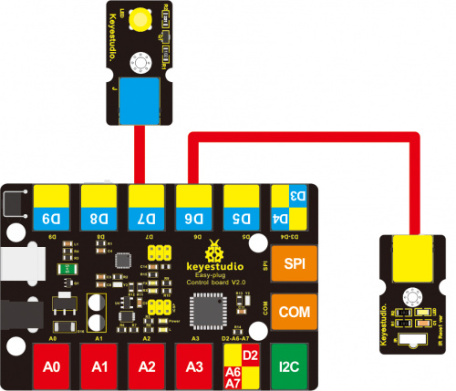
Hookup Guide Connect the EASY Plug Infrared receiver module and LED module to control board using RJ11 cables.
Test Code
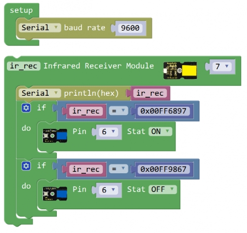
What You Should See Upload success, press the key 1 on your remote controller, LED lights up. Then press the key 2, LED is turned off.
Little Knowledge: If you want to change another remote control key, you should be able to change your remote key decoding. Shown below.
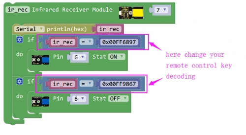
After that, upload the code again and have a try.
Last updated
Was this helpful?