OpenELAB Wiki
  • 🚀Welcome to Our Wiki!
  • 1️⃣M5Stack
    • M5Stack Cardputer Kit w /M5StampS3
    • M5Stack Dial - ESP32-S3 Smart Rotary Knob
    • M5StickC PLUS2 ESP32 Mini IoT Development Kit
    • M5StickC PLUS ESP32-PICO Mini IoT Development Kit
    • M5Stack Core2 ESP32 IoT Development Kit for AWS IoT Kit
    • M5Stack Core2 ESP32 IoT Development Kit
    • M5Stack AtomS3 Lite ESP32S3 Dev Kit
    • M5Stack ATOMS3 Dev Kit w/ 0.85-inch Screen
    • M5Stack ATOM TailBat - Battery Accessory for ATOM
    • M5Stack ATOM Matrix ESP32 Development Kit
    • M5Stack ATOM Lite ESP32 IoT Development Kit
    • M5Stack ATOM Echo Smart Speaker Development Ki
    • M5Stack ENV III Unit with Temperature Humidity Air Pressure Sensor
    • M5Stack COMMU Module Extend RS485/TTL CAN/I2C Port
    • M5Stack ATOMIC PoE Base W5500
    • M5Stack Time-of-Flight Distance Unit (VL53L1X)
    • M5Stack LoRa Unit with Antenna(E220)
    • M5Stack Glass 2 Unit w/ 1.51inch Transparent OLED
    • M5Stack Temperature, Humidity, Pressure and Gas Sensor (BME688)
    • M5Stack Temperature Humidity Air Pressure Sensor (SHT40+BMP280)
    • M5Stack H-bridge Unit v1.1 (STM32F030)
    • M5Stack 8-Channel Servo Driver Unit (STM32F030)
    • M5Stack ATOMIC TTL-RS485 Base
    • M5Stack ATOMIC PortABC Extension Base
    • M5Stack Ext Encoder Unita (STM32F030)
    • M5Stack Single-phase DC SSR Unit (CDG1. 1DD-10A)
    • M5Stack Speaker 2 Hat (MAX98357)
    • M5Stack Glass Unit w/ 1.51inch Transparent OLED
    • M5StickC Vibration HAT
    • M5Stack RCA Audio/Video Composite Unit
    • M5Stack Barometric Pressure 2 Unit (QMP6988)
    • M5Stack 8-Angle Unit with Potentiometer
    • M5Stack 8-Encoder Unit (STM32F030)
    • M5Stack Flashlight Unit
    • M5Stack NCIR 2 Thermometer Unit (MLX90614)
    • M5Stack M5StickV K210 AI Camera (Without Wifi)
    • M5Stack Thermal Camera 2 Unit (MLX90640) -110 Degree FoV
    • M5Stack USB TypeC2Grove Unit
    • M5Stack Scales Unit with 20kgs Range (HX711)
    • M5Stack I/O Hub 1 to 6 Expansion Unit (STM32F0)
    • M5Stack Keyboard Programmable Unit V1.1 (MEGA8A)
    • M5Stack Red 7-Segment Digit Clock Unit
    • M5Stack Mechanical Key Button Unit
    • M5Stack ESP32 Ethernet Unit with PoE
    • M5Stack Encoder Unit
    • M5Stack MQTT PoE Unit with PoE Port
    • M5Stack Unit CamS3 Wi-Fi Camera 5MP
    • M5Stack Ultrasonic Distance Unit I2C
    • M5Stack Ultrasonic Distance Unit I/O
    • M5Stack Passive Buzzer Unit
    • M5Stack 2-Channel SPST Relay Unit
    • M5Stack Tube/Air Pressure Unit
    • M5Stack MQTT Unit with RJ45 Port
    • M5Stack Gesture recognition sensor
    • M5Stack Fader Unit with B10K Potentiometer
    • M5Stack I2C Hub 1 to 6 Expansion Unit
    • M5Stack Real Time Clock (RTC) Unit
    • M5Stack OLED Unit 1.3"Display
    • M5Stack RF UNIT 433MHz Transmitter
    • M5Stack ATOM Socket Kit
    • M5Stack Watering Unit with Mositure Sensor and Pump
    • M5Stack Digital RGB LED Strip
    • M5Stack M5StickC 18650C
    • M5Stack M5StickC SERVO HAT
    • M5Stack M5StickC Fingerprint HAT
    • M5Stack M5StickC ToF HAT
    • M5Stack Mini GPS/BDS Unit
    • M5Stack Finger Print Sensor Unit
    • M5Stack DAC Converter Digital
    • M5Stack RGB LED Unit
    • M5Stack Mini 3A Relay Unit
    • M5Stack Earth Moisture Sensor Unit
    • M5Stack Color Sensor RGB Unit
    • M5Stack Mini Angle Unit Rotary Switch
    • M5Stack PIR Motion Sensor
    • HEX RGB LED Board
    • M5Stack LoRa Module (433MHz) v1.1
    • M5Stack ATOMS3R Camera Kit
    • M5Stack ATOMS3R Development Kit
    • M5Stack Roller485 Lite Unit
    • M5Stack ATOMS3R Proto Kit
    • M5Stack M5Stamp Fly with M5StampS3
    • M5Stack M5Atom Joystick with M5AtomS3
    • M5Stack ATOMS3R Camera (OV3660)
    • M5Stack Battery Module
    • M5Stack Unit Cam Wi-Fi Camera
    • M5Stack PIR Motion Sensor
    • M5Stack RFID 2 Unit
    • M5Stack Mini Dual
    • M5StickV K210 AI Camera
    • M5Stack Glass 2 Unit
    • Hall Effect Unit
    • Voltage and Amperage Meter
    • M5Stack ENV Pro Unit
    • NCIR 2 Thermometer Unit
    • M5GO Battery Bottom2
    • M5Stack USB Module
    • M5Stack LoRa Module
    • M5Stack LLM Module
    • M5Stack Timer Power Unit
    • M5Stack 8-Encoder Unit
    • M5Stack LoRa Module
    • M5Stack 8-Angle Unit
    • Gesture recognition sensor
    • M5StickC ENV III HAT
    • M5StickC DAC 2 Hat
    • M5Stack Color Sensor
    • Time-of-Flight Distance
    • M5StickC ToF HAT
    • Neo HEX 37 RGB LED
    • M5Stamp ESP32S3
    • Tube/Air Pressure
    • 8-Channel Servo Driver
    • M5Stack Mini Angle Unit
    • M5Stack Mini Infrared Emitter
    • M5Stack NanoC6 Dev Kit
    • M5Stack ENV III Unit
    • Temperature Humidity Air Pressure
    • M5Stack 2-Channel SPST
    • M5Stack BLDC Motor
    • M5Stack Ultrasonic
    • M5Stack M5Stamp
    • M5Stack DAC
    • M5Stack Mini CAN Unit
    • M5Stack Ambient Light Sensor
    • M5Stack PIR Hat
    • M5Stack Speaker
    • M5Stack Weight
    • M5Stack Core2
    • M5StickC PLUS
    • M5Stack Barometric Pressure
    • M5Stack Ambient Light Sensor
    • M5Stack Passive Buzzer
    • M5Stack Mechanical Key Button
    • M5Stack Limit Switch
    • M5StickC Vibration HAT
    • PM5Stack RCA Audio/Video
    • M5Stack Flashlight
    • M5Stack COMMU Module Extend
    • M5Stack M5StampS3 with 1.27 Header Pin
    • M5Stack M5StampS3 with 2.54 Header Pin
    • ATOMIC Barcode/QR-Code Scanner
    • M5Stack Station ESP32 IoT
    • M5Stack ESP32 Core Ink
    • M5Paper ESP32 Development Kit
    • ATOMIC CANBus Base
    • M5Stack M5StickC ADC Hat
    • M5Stack LoRa
    • M5Stack H-bridge
    • ATOMIC GPS Base
    • M5Stack Ext Encoder
    • M5Stack Single-phase DC SSR
    • M5Stack Glass Transparent OLED
    • M5Stack Thermal Camera
    • M5Stack USB TypeC2Grove
    • M5Stack I/O Hub
    • M5Stack CardKB Mini Keyboard
    • M5Stack Red 7-Segment Digit Clock
    • M5Stack Extend I/O
    • M5Stack I2C Joystick
    • M5Stack ESP32 Ethernet
    • M5Stack 8-Channel Servo Driver
    • M5Stack Encoder
    • M5Stack MQTT PoE
    • M5Stack Ultrasonic
    • M5Stack I2C Hub
    • M5Stack MQTT
    • M5Stack Fader
    • M5Stack Real Time Clock
    • M5Stack OLED
    • M5Stack RF Unit
    • M5Stack Watering Unit
    • M5Stack Digital RGB LED
    • M5Stack JoyC Omni-directional Controller
    • M5Stack SERVO HAT
    • M5Stack Fingerprint HAT
    • M5Stack Finger Print Sensor
    • M5Stack RGB LED
    • M5Stack Mini 3A Relay
    • M5Stack Earth Moisture Sensor
    • M5Stack 1 to 3 HUB Expansion
    • M5Stack RS485 to TTL Converter
    • HEX RGB LED Board
    • M5Stack LoRa 433MHz with Antenna
    • M5Stack NB-IoT with Antenna
    • M5Stack Battery Bottom 110mAh
    • M5Stack Programmable Power Supply Module
    • M5Stack LAN Module
    • M5Stack RCA Audio/Video Module
    • M5Stack LAN Module W5500
    • M5Stack IoT Base
    • M5Stack AC Power Base
    • M5Stack GRBL Module Stepmotor Driver
    • M5Stack COM.LTE Module
    • M5Stack Proto Pegboard Module
    • M5Stack BaseX EV3 motor
    • M5Stack Proto Module
    • M5Stack M5GO/FIRE Battery
    • M5Stack PoE Camera with Wi-Fi
    • M5Stack UnitV K210 AI Camera
    • M5Stack UnitV2 M12 with Cameras
    • M5Stack ESP32 PSRAM Timer Camera Fisheye
    • M5Stack ESP32 PSRAM Timer Camera
    • M5Stack Universal IOT Experiment Kit
    • M5Stack Scale Kit
    • M5Stack AGV Mini Carkit Mecanum Wheels
    • M5Stack 6060-PUSH Linear Motion Control
    • M5Stack BugC2 w/ M5StickC PLUS2
    • M5Stack RoverC Pro
    • M5Stack BALA2 Fire Self-balancing Robot Kit
    • M5Stack 16 PCS M3 Screw
    • M5Stack Unbuckled Grove Cable
    • M5Stack RS485T T-Shaped Connector
    • M5Stack CM4Stack Development
    • M5Stack CoreS3 ESP32S3 loT Development
    • M5Stack M5StickC PLUS2 with Watch Accessories
    • M5Stack Mini GPS/BDS
    • M5Stack M5Stick T-Lite Thermal Camera
    • M5Stack UnitV2 - The standalone AI Camera
    • M5Stack ESP32 Fisheye Camera
    • M5Stack Voltage and Amperage Meter
    • M5Stack CardKB Mini Keyboard
    • M5Stack M5Stamp C3 (5pcs)
  • 2️⃣ESP
    • ESP8266EX
    • ESP8266 ESP-01S WiFi module
    • ESP32-WROOM-32E
    • ESP32-WROOM-32 Wifi Bluetooth Type-C Dev Kit
    • ESP32-S3-WROOM-1U
    • ESP32-S3-Nano - Development Board
    • ESP32-S3 Rotary Switch LCD 2.1 inch Round LCD Screen
    • ESP32-PICO-D4
    • ESP32-H2
    • ESP32-CAM Camera Module
    • ESP32-C6
    • ESP32 NODEMCU Module WiFi Development Board with CP2102
    • ESP32 D1 Mini Nodemcu Development Board
    • D1 Mini Nodemcu with ESP8266-12F WLAN module
    • D1 Mini V3 Nodemcu with ESP8266-12F WLAN module
    • Seeed Studio XIAO ESP32S3 WIFI Dev Board
    • XIAO SAMD21 Arduino Microcontroller
    • XIAO RP2040
    • XIAO ESP32-C3 WIFI
    • XIAO ESP32-C6 WIFI
    • 6x10 RGB MATRIX
    • XIAO nRF52840 Sense
  • 3️⃣DRONE / FPV
    • ZD850 850mm Compact Folding Hexacopter Drone Frame Kit Full Carbon Fiber
    • DXW 4114 400KV High Power Brushless Motors
    • DXW D4250 800KV 3-7S Brushless Motor
    • DXW D3536 1200KV 2-4S Brushless Motor
    • DXW A2212/C2826 3.17mm Outrunner Brushless Motor
    • Hobbywing Skywalker V2 Brushless ESC Speed Controller
    • Pixhawk PX4 Flight Controller
    • Holybro Pixhawk 6C
    • GPS Stand
    • Holybro GPS M8N
    • Holybro GPS M9N
    • Holybro GPS M10N
    • Radiolink M8N SE100 GPS Module
    • Radiolink M10N SE100 GPS for PX4/Pixhawk 2.4.8
    • Mateksys GNSS M9N-5883
    • MFD Crosshair Color OSD
    • 2 Pair Carbon Fiber CW CCW Propellers
    • 3-Axis Brushless Gimbal Frame With Motors & Storm32 Controller
    • 2-Axis Brushless Gimbal Frame With Motors & Storm32 Controller
    • RadioLink AT10 II 2.4Ghz 10CH RC Transmitter
    • Radiolink Mini PIX V1.2 Flight Controller M10N GPS TS100 SE100 (Pixhawk Alternative)
    • 2Pcs OVONIC 3S 4S 6S Lipo Battery For RC FPV
    • Gens ACE Lipo Battery with T/XT60 Plug
    • LiPo Battery 3S 11.1V for RC Drone
    • Holybro PM02 V3 Power Module 12S
    • Holybro PM06 V2 Power Module 14S
    • Holybro PM07 V2 Power Module 14S
    • Holybro Power Distribution Board (PDB)
    • Mateksys Power Distribution Board (PDB) XT60 W/ BEC 5V & 12V
    • Hawk eye FPV Monitor 5.8G 48CH 4.3 inch FPV HD Monito
    • RUSH TANK MAX SOLO 5.8GHz 2.5W High Power 48CH VTX Video Transmitter
    • RUSH TANK SOLO 5.8G VTX Video Transmitter CNC shell 1.6W
    • Happymodel EP1 Dual Receiver 2.4Ghz ExpressLRS RX
    • Mateksys BEC12S-PRO, 9-55V TO 5V/8V/12V-5A
    • ZD850 850mm 6-axis Drone with 6kg Payload
    • ZD550 550mm 4-axis Drone with 6kg Payload
    • YRRC 5.8G 2.5W 40CH VTX Drone FPV Analog Image Transmission
    • Hawkeye Firefly 8SE/8S 4K Screen WiFi FPV Action Camera
  • 4️⃣RASPBEERY PI
    • Raspberry Pi Pico W Wireless RP2040 MCU Board
    • Raspberry Pi 5
    • Raspberry Pi 4B
    • ELAB Raspberry Pi Card Reader
    • ELAB Raspberry Pi 5 Active Cooler
    • ELAB Raspberry Pi 4/5 Case (Acrylic case)
    • ELAB Raspberry Pi 4 Heat Sink (Copper)
    • Camera for Raspberry Pi
    • XIAO RP2350 Onboard RGB LED, Arm Cortex-M33 and Hazard3 RISC-V(Pre-Order)
    • Raspberry Pi Pico 2 RP2350
    • Seeed Studio Grove Starter Kit for LinkIt ONE
    • Seeed Studio ReSpeaker USB Mic Array
    • Raspberry Pi Zero 2W with Bluetooth 4.2 Onboard Antenna
    • Raspberry Pi Zero WH WiFi/Bluetooth 4.1 Bluetooth Low Energy
    • Seeed Studio XIAO RP2040 Supports Arduino
    • M.2 HAT for Raspberry Pi 5
    • EdgeBox Raspberry Pi IoT Edge Device 4GB RAM 32GB eMMC WiFi
    • Raspberry Pi Compute Module 4 with WiFi
    • Raspberry Pi 4 ReSpeaker Intelligent Speech Recognition 2 Microphone
    • Raspberry Pi 5 Vision Car AI Development Board Camera Recognition WIFI Kit
    • Waveshare RM500U-CNV Raspberry PI 5G/4G/3G Hat
    • Hailo-8 M.2 AI Accelerator Module Suitable for Raspberry Pi 5
    • Waveshare ESP8266 for Raspberry Pi Pico Wifi Module TCP UDP
    • Waveshare MAX-M8Q GNSS HAT for Raspberry Pi
    • Waveshare SX1262 LoRa HAT for Raspberry UART
    • Waveshare SX1268 LoRa HAT for Raspberry UART
    • Waveshare SIM7070G NB-IoT / Cat-M / GPRS / GNSS HAT for Raspberry Pi
    • Waveshare SIM7600G-H M.2 4G HAT for Raspberry Pi 4G/3G/2G GNSS
    • Waveshare SIM7600CE-CNSE 4G HAT for Raspberry Pi 4G 3G 2G GNSS
  • 5️⃣ARDUINO
    • ATmega328DIP Board Microcontroller Board
    • OpenELAB EASY PLUG RGB TCS34725 Color Sensor Module I2C
    • OpenELAB EASY PLUG Micro SD TFT card Read and Write Module
    • OpenELAB EASY PLUG CCS811 CO2 Air Quality Sensor
    • OpenELAB EASY PLUG SR01 Ultrasonic Sensor
    • OpenELAB EASY PLUG Education Robot Car Kit
    • OpenELAB EASY PLUG Sensor Learning Kit for Arduino
    • OpenELAB EASY PLUG Ultimate Starter Kit for Arduino
    • OpenELAB KEYBOT Programmable Education Robot Control Board
    • OpenELAB RJ11 EASY Plug Main Control Upgrade Board V2.0
    • OpenELAB Desktop Mini Bluetooth Smart Robot Car Kit V3.0
    • OpenELAB 4WD Mechanical Arm Robot Smart Car for Arduino
    • OpenELAB 4DOF Mechanical Arm Robot Car Learning Starter Kit
    • OpenELAB 4WD Mechanical Arm Robot Smart Car for Arduino
    • OpenELAB Desktop Mini Bluetooth Smart Robot Car Kit V3.0
    • OpenELAB RJ11 EASY Plug Main Control Upgrade Board V2.0
    • OpenELAB KEYBOT Programmable Education Robot Control Board
    • OpenELAB EASY PLUG Ultimate Starter Kit for Arduino
  • 6️⃣DISPLAYS
    • 1.3 inch OLED I2C 128 x 64 Pixel Display
    • 0.91 inch OLED I2C Display 128 x 32 pixels
    • WT32S3-86S touch display screen with temp and humidity sensor
    • LCD Display 1602 I2C
    • HW-140 DC-DC Buck Boost Converter Step Up/Down, LCD display
    • HD44780 2004 LCD Display Bundle 4x20 characters
    • ESP32-S3 Rotary Switch LCD 2.1 inch Round LCD Screen
    • 8*8 Matrix LED Display Module
    • 4 digit 7-segment LED Display
    • 3.5-inch 320x480 resistive touch display
    • 3.5-inch 320x480 capacitive touch display
    • 1.77 inch Spi TFT Display and 128x160 Pixels
    • 1.8 inch Spi TFT Display 128 x 160 pixels
    • 1 Digit 7-Segment LED Display 1 inch 25.4 mm
    • 0.96 inch OLED SSD1306 Display I2C 128 x 64 pixels
    • Waveshare 10.1 inch IPS Capacitive Touch Display
    • Waveshare 10.1 inch QLED Touch Display
    • Waveshare 9.7 inch IPS Capacitive Touch Display
    • Waveshare 10.1 inch IPS Capacitive Touch LCD
    • Waveshare 9.3 inch LCD Capacitive Touch Display High Brightness
    • Waveshare 9 inch QLED Quantum Dot Display
    • Waveshare 8 inch 2K IPS Capacitive Touch Display
    • Waveshare 8DP-CAPLCD 8 inch Capacitive Touch Display
    • Waveshare 7.9 inch IPS LCD Touch Screen, 400×1280 HDMI
    • Waveshare 8 inch DSI LCD Display Touch Screen I2C
    • Waveshare 7 inch IPS Integrated Display, With Touch Function
    • Waveshare 7HP-CAPQLED 7 inch QLED Quantum Dot Display
    • Waveshare 7 inch Capacitive Touch Screen HDMI
    • Waveshare 7 inch Capacitive Touch Screen with Case HDMI
    • 2.8inch USB Monitor,Water Cooler Screen/ PC Case Secondary Screen
    • Waveshare 5inch Desktop RGB Ambient Screen
    • Waveshare 5inch IPS Round Touch DisplayHDMI
    • Waveshare 5.5inch 2K Touch LCD Display HDMI
    • 2.1 inch USB Monitor, Water Cooler Screen/ PC Case Secondary Screen
    • Waveshare 8.8inch Desktop RGB Ambient Screen Type-C
    • Waveshare 8inch Desktop RGB Ambient Screen Type-C
    • Waveshare 7 inch Desktop RGB Ambient Screen
    • Waveshare 5inch HDMI Touch Screen LCD with Bicolor Case
    • Waveshare 65K RGB General 1.28inch Round LCD Display Module
    • 0.96 inch OLED Display Module, SPI / I2C Communication
    • 1.5 inch LCD Display Module, IPS Panel SPI 262K colors
    • Waveshare 1.8inch colorful display module for micro:bit
    • Waveshare 3.5inch RPi LCD (A)
    • Waveshare 5 inch LCD Touch Screen Display for Raspberry Pi
    • Waveshare 1.47inch LCD Display Module SPI
    • 7.3 inch 7 Color E-Paper
    • Waveshare 15.6 inch QLED Touch
    • Waveshare 7.5 inch NFC-Powered
  • 7️⃣CAMERAS
    • OV5640 Camera Board (A), 5 Megapixel (2592x1944)
    • OV2640 Camera Board (1622x1200)
    • Hawkeye Firefly 8SE/8S 4K Screen WiFi FPV Action Camera
    • ESP32-CAM Camera Module
    • DFRobot Gravity Huskylens AI Camera
    • IMX335 5MP USB Camera (B)
  • 8️⃣SENSORS
    • Rotation Sensor
    • WT32S3-86S touch display screen with temp and humidity sensor
    • Vibration Sensor
    • Ultrasonic Sensor
    • Thermistor Module
    • Soil Temperature and Humidity Module
    • Soil Moisture Sensor Hygrometer Module V1.2 capacitive
    • Shock Sensor Module
    • MQ-135 Gas Sensor
    • Motion Sensor Motion Detection Module HC-SR501 PIR
    • DHT11 Temperature-Humidity Sensor
    • DHT22 AM2302 Temperature sensor and humidity sensor
    • Current Sensor ACS712ELC-20A
    • VL53L0X Time-of-Flight (TOF) Laser distance sensor
    • GY-521 MPU-6050 3-axis gyroscope and acceleration sensor
    • DS18B20 digital temperature sensor
    • BME280 Humidity Pressure Temperature Sensors
  • 9️⃣IOT / COMMUNICATION
    • NodeMCU Lua Amica Module V2 ESP8266 ESP-12F WIFI
    • SIM7028 NB-IoT HAT
    • NRF24L01 with 2.4 GHz
    • Ai-Thinker AiPi-Eyes-S1 WifFi Camera
    • Ai-Thinker AiPi-Eyes-S2 WifFi Camera
  • 🔟MOTORS
    • CyberGear micromotor instruction manual
    • Servo Motor (SG90)
    • 5V DC Stepper Motor & ULN2003 Driver Board
    • 130 DC Motor
    • Xiaomi CyberGear Micromotor
  • 🇰🇳KITS
    • mBot Mega
  • ⚡POWER
    • HW-140 DC-DC Buck Boost Converter Step Up/Down, LCD display
    • MT3608 DC-DC power supply adapter step up module
    • LM2596S Step-down DC-DC Buck Converter
    • LM2596S DC-DC power supply adapter step down module
    • Hi-Link DC-DC 5V to xxV 1W Mini Converter Isolated Power Supply
    • Hi-Link AC-DC 5W Converter Power Supply
    • Hi-Link AC-DC 220V to xxV 3W Converter Power Supply
    • SunLit Austa Solar Module
  • 🔌ACCESSORIES
    • 4 digit 7-segment LED Display
    • 5V LED Traffic Signal Module
    • LED Ring 5V RGB WS2812B 12-Bit 50mm
    • 3D MKS Gen V1.4 Printer
    • USB 3.2 To 5GbE Adapter (WP-UT5) Realtek RTL8157
  • Heygears Reflex User Guide
Powered by GitBook
On this page
  • Waveshare ESP8266 for Raspberry Pi Pico Wifi Module TCP UDP
  • Product Link
  • Overview
  • Features
  • Specification
  • Pinout
  • Dimensions
  • Quick start
  • MicroPython Example
  • Resource
  • Pico Quick Start
  • Video Tutorial
  • Text Tutorial

Was this helpful?

PreviousHailo-8 M.2 AI Accelerator Module Suitable for Raspberry Pi 5NextWaveshare MAX-M8Q GNSS HAT for Raspberry Pi

Last updated 8 months ago

Was this helpful?

Waveshare ESP8266 for Raspberry Pi Pico Wifi Module TCP UDP


Product Link

Overview

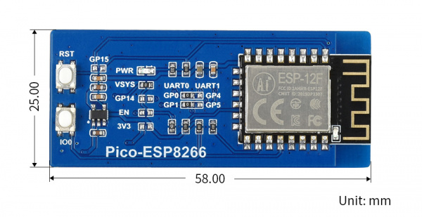
The Pico-ESP8266 is a WiFi expansion module designed for Raspberry Pi Pico, which can be controlled via UART AT command, and supports TCP/UDP communication protocol. It is an easy solution to enable WiFi feature for Raspberry Pi Pico, suitable for sorts of IoT communication projects.

Features

  • Standard Raspberry Pi Pico header supports Raspberry Pi Pico series.

  • UART communication, controlled via AT command, helps you get started quickly.

  • Supports STA, AP, and STA+AP three WiFi operating modes, embedded LWIP protocol stack, supports TCP/UDP communication.

  • Based on ESP8266 module, four-layers process, enhanced impedance matching, stronger signal, more stable connection.

  • 2 x functional buttons, convenient for the user to update AT firmware through Raspberry Pi Pico.

  • Comes with online development resources and manual (Raspberry Pi Pico C/C++ and MicroPython examples).

Specification

  • Communication interface: UART

  • UART baud rate: 115200 bps

  • WIFI standard: IEEE 802.11b/g/n

  • Frequency range: 2400 ~ 2483.5MHz

  • WIFI operating mode: WiFi STA, WiFi AP, WiFi STA+AP

  • Antenna: PCB antenna

  • Operating voltage: 3.3V

  • Operating temperature: -40°C ~ 85°C

  • Dimensions: 58 x 25mm

Pinout

Dimensions

Quick start

Hardware connection

  1. Press and hold the BOOTSEL button of Pico, the pico will be recognized as a movable disk, copy the dev_cdc_ports.uf2 file from demo codes to the Pico, the Pico will automatically restart and work as the USB to serial adapter.

  2. Connect the Pico_EPS8266 board to Pico, then connect the Pico to PC by USB cable.

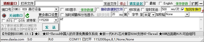
  3. Open an SSCOM software, choose the correct COM port, and set the baud rate to 115200.

  4. Test the module by AT command.

AT commands

  • 1. AT:

AT
Response:
AT
OK
  • 2. AT+RST Restart device:

AT+RST
Response:
AT+RST
OK
  • 3. AT+GMR Check version:

AT+GMR
Response:
AT+GMR
AT version:1.2.0.0(Jul  1 2016 20:04:45)
SDK version:1.5.4.1(39cb9a32)
Ai-Thinker Technology Co. Ltd.
v1.5.4.1-a Nov 30 2017 15:54:29
OK

TCP Client

  • 1. Configure WiFi mode.

AT+CWMODE=3	//softAP+station mode
Response: :
OK
  • 2. Connect to the router.

AT+CWJAP="SSID","password"	//SSID and password of the router
Response: :
AT+CWJAP="SSID","password"
OK

If it succeeds in connecting the WIFI, it will respond and get an IP address.

WIFI CONNECTED
WIFI GOT IP
  • 3. Check the IP address of ESP8266.

AT+CIFSR
Response: :
+CIFSR:APIP,"192.168.4.1"
+CIFSR:APMAC,"1a:fe:34:a5:8d:c6"
+CIFSR:STAIP,"192.168.3.133"
+CIFSR:STAMAC,"18:fe:34:a5:8d:c6"

OK
  • 4. PC and ESP8266 are connected to the same router, use the network debugging tool on the PC end, and establish a TCP server.

For example, build a server on a PC with IP address 192.168.3.116 and port 8080.

  • 5. ESP8266 works as a TCP client and connects to the server.

AT+CIPSTART="TCP","192.168.3.116",8080		 //protocol, server IP and port
Response :
CONNECT
OK
  • 6. ESP8266 device ends data of a specified length to the server.

AT+CIPSEND=4                            //set date length which will be sent, such as 4 bytes	
>test                                   //enter the data, no CR
Response :
Recv 4 bytes
SEND OK
  • 7. The data is printed if ESP8266 receives data from the server.

+IPD,n:xxxxxxxxxx				//received n bytes, data=xxxxxxxxxxx
  • 8. Enable the transparent transmission mode, data can be directly transmitted

AT+CIPMODE=1
Response :
OK
  • 9. If the transparent transmission mode is enabled, data can be directly transmitted

AT+CIPSEND	

>	 //From now on, data received from UART will be	transmitted to	the server automatically.
  • 10. Exit sending data:

If +++ is detected in a single packet of data during transparent transmission, the system stops transparent transmission.

- If you use the keyboard to type +++, it may take too long and is not considered as three consecutive + s. You are advised to use a serial port tool to send +++ at a time and not carry invisible characters such as Spaces or newlines. - Please send the next AT command AT least one second later

  • 11. Exit the transparent transmission mode.

AT+CIPMODE=0
Response :
OK
  • 12. Disconnect TCP.

AT+CIPCLOSE
Response :
CLOSED
OK

TCP Server

  • 1. Configure WiFi mode:

AT+CWMODE=3	//softAP+station mode
Response :
OK
  • 2. Connect to router:

AT+CWJAP="SSID","password"	//SSID and password of the router
Response :
OK
  • 3. Check the IP address of the ESP8266 device:

AT+CIFSR
Response :
+CIFSR:APIP,"192.168.4.1"
+CIFSR:APMAC,"1a:fe:34:a5:8d:c6"
+CIFSR:STAIP,"192.168.3.133"
+CIFSR:STAMAC,"18:fe:34:a5:8d:c6"
OK
  • 4. Enable multiple connection:

AT+CIPMUX=1
Response :
OK

Note: If "IPMODE must be 0" appears, it is necessary to disconnect ESP8266 and then enter the command. If not, press the button or power off to restart the module and then operate it again.

  • 5. Build TCP server

AT+CIPSERVER=1	 	 //	default	port	=	333
Response :
OK
  • 6. The PC and THE ESP8266 are connected to the same router. Use the network debugging tool on the PC to establish a TCP client and connect to the TCP server of the ESP8266.

  • 7. Send data:

//ID number of connection is	defaulted	to be 0.
AT+CIPSEND=0,4   //send 4	bytes to connection NO.0
>test            //enter the	data, no CR
Response :
Recv 4 bytes

SEND OK
  • 8. When the ESP8266 device receives data from the server, the following message is displayed:

+IPD,0,n:xxxxxxxxxx	 //received n bytes,	 data=xxxxxxxxxxx
  • 9. Disconnect TCP:

AT+CIPCLOSE
Response :
CLOSED
OK

UDP

UDP transmission does not distinguish between server and client and is established by the AT+CIPSTART command.

  • 1. Configure WiFi mode.

AT+CWMODE=3	//softAP+station mode
Response :
OK
  • 2. Connect to the router.

AT+CWJAP="SSID","password"	//SSID and password of router
Response :
AT+CWJAP="SSID","password"
OK

If the connection is normal, it may prompt you to connect to WIFI and obtain the IP address.

WIFI CONNECTED
WIFI GOT IP
  • 3. Example Query the IP address of the ESP8266.

AT+CIFSR
Response :
+CIFSR:APIP,"192.168.4.1"
+CIFSR:APMAC,"1a:fe:34:a5:8d:c6"
+CIFSR:STAIP,"192.168.3.133"
+CIFSR:STAMAC,"18:fe:34:a5:8d:c6"

OK
  • 4. The PC and the ESP8266 are connected to the same router. Use the network debugging tool on the PC to set up a TCP server.

For example, build a server on a PC with IP 192.168.3.116, and the port is set as 8080.

  • 5. Enable multiple connections.

AT+CIPMUX=1
Response :
OK

Note: If "IPMODE must be 0" appears, it is necessary to disconnect ESP8266 and then enter the command. If not, press the button or power off to restart the module and then operate it again.

  • 6. Create a UDP transport. For example, to assign a joined number of 4, the instruction is as follows:

AT+CIPSTART=4,"UDP","192.168.101.110",8080,1112,0
Response :
4, CONNECT	

OK

Note: About the command:

  • "192.168.101.110", 8080 is the remote IP and port transmitted, that is the UDP port built in step 4;

  • 1112 is the local UDP port of ESP8266, it is configurable, or a random port

  • 0 Indicates that after the current UDP transmission is established, the UDP remote device will not be changed by other devices. Even if other devices send data to ESP8266 UDP port 1112 through UDP protocol, the remote end of THE UDP transmission no. 4 of ESP8266 will not be replaced. If the command "AT+CIPSEND=4, X" is used to send data, the current PC will still receive the data.

  • 7. Send data

AT+CIPSEND=4,7	 //Send 7 bytes to transmission NO.4	
>UDPtest  // enter the data, no CR
Response :
Recv 7 bytes
SEND OK

Note:

• When sending data, if the number of bytes entered exceeds the set length(n): - The system prompts BUSY, sends the first N bytes of data, and responds SEND OK when the sending is complete. - The data that exceeds the length is considered invalid and is not accepted.

  • 8. Receive data. When the ESP8266 device receives data from the server, the following information is displayed:

+IPD,4,n:xxxxxxxxxx		 //received n bytes,	data=xxxxxxxxxxx
  • 9. If the transparent transmission mode is enabled, data can be directly transmitted.

AT+CIPMODE=1
Response :
OK
  • 10. The ESP8266 device transmits data to the server through transmission

AT+CIPSEND	

>	 //From now on, data received from UART will be	transmitted to the server automatically.
  • 11. Exit sending data:

If +++ is detected in a single packet of data during transparent transmission, the system stops transparent transmission.

- If you use the keyboard to type +++, it may take too long and is not considered as three consecutive + s. You are advised to use a serial port tool to send +++ at a time and not carry invisible characters such as Spaces or newlines. - After that, send the next AT command AT least one second later.

  • 12. Exit the transparent transmission mode

AT+CIPMODE=0
Response :
OK
  • 13. Disconnect UDP transmission

AT+CIPCLOSE=4
Response :
4, CLOSED
OK

MicroPython Example

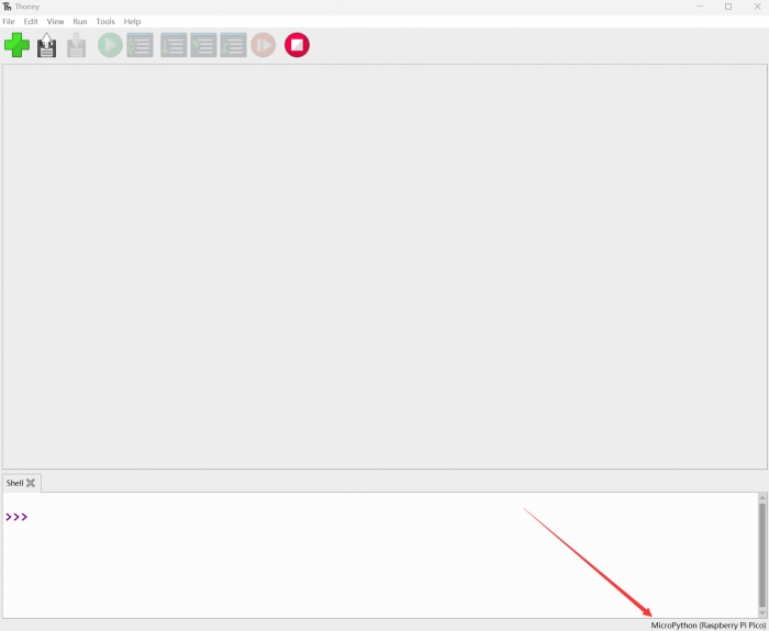
Before Pico can run MicroPython programs, you need to download the MicroPython firmware, install the Thonny IDE, and configure the motherboard environment with the Rasberry Pi option.

TCP Client

  • Open the TCP&UDP test tool, create the server, and start the server.

  • Open tcp_client.py in Thonny IDE and change the SSID and password to the actual WiFi account and password. Change the values of ServerIP and Port in the program to the IP and Port of the actual TCP server.

  • Click run program. After running, the program will connect to WiFi and send data to the server. The information sent by the server is displayed in the shell.

TCP Server

  • Open the tcp_server.py program in Thonny IDE and change SSID and password values to the actual WiFi account password.

  • Click to run the program. After the program runs, it will connect to WiFi and start the server. The SHELL displays the STAIP address of ESP8266.

  • Open the TCP&UDP test tool, create a connection, set the type to TCP, and target IP to the STAIP address displayed in the shell, port 8080.

  • Click the "connect" button to connect to the server. After a normal connection, the icon changes from a blue dot to a green triangle.

UDP

  • Open the TCP&UDP test tool, create a connection, and select UDP as the type, the destination IP address is the STAIP address displayed in the shell after running the program, the port is 1112, and the local port is 8087. Select Create and Connect.

  • Open the tcp_server.py program in Thonny IDE and change the SSID and password to the actual WiFi account and password. Set remote_IP to the actual IP address of the computer

  • After the program runs, it will connect to WiFi and send data to UDP on the computer side. Enter a string in the send area and send it. ESP8266 receives the message and sends it back for display in the receiving area. The shell port will also display the received information.

C/C++ codes

  • C/C++ is compiled in Raspberry PI. This step can be skipped if the Pico compilation environment has been configured for Raspberry PI. If the Pico compilation environment has not been configured, perform the following operations.

wget 
chmod +x pico_setup.sh
./pico_setup.sh
  • Download the demo codes:

cd ~
wget  
unzip Pico-ESP8266.zip
cp -r Pico-ESP8266/c/pico-esp8266  pico
  • Before compiling the program, you need to modify the program and change the values of SSID and password to the actual WiFi account password. Change the values of ServerIP and Port in the program to the IP and Port of the actual TCP server.

  • Compiler:

cd pico/pico-esp8266/build
cmake ..
make

Download AT Firmware

  • Hold the Pico's BOOTSEL button and power on. The computer will recognize a USB flash drive and copy the dev_CDC_ports.uf2 file from the sample program to the flash drive to download the program. The Pico will become a USB-to-serial device.

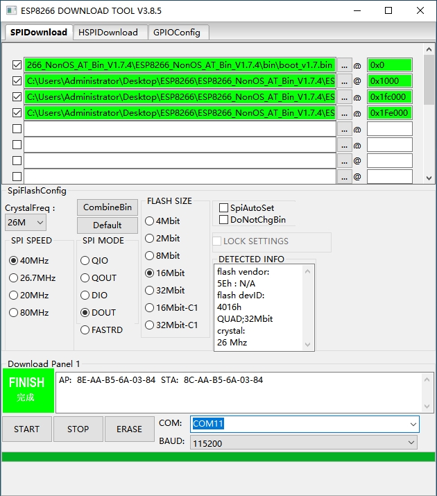
  • Run the flash_download_tool software.

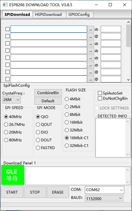
  • The factory default of the module is C1.5.4.1 AT firmware 32Mbit version. Select ai-thinker_esp8266_dout_32mbit_V1.5.4.1 -a_20171130.bin and set the address to 0x0. Set SPI SPEED to 40MHz, SPI MODE to DOUT, and FLASH SIZE to 32Mb-C1.

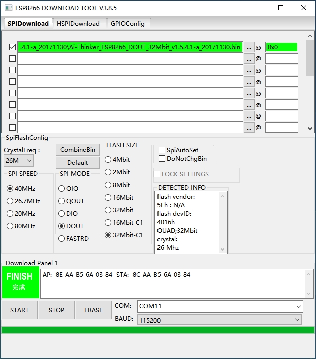
  • Hold the IO0 button of the PICo-ESP8266 and then press the RESET button to enter download mode. Select the corresponding serial port and set the baud rate to 115200. Click START and wait for the download to complete.

  • To set the AT firmware for nonOS_AT_BIN_V1.7.4, follow the following figure.

Resource

Document

Examples

Software

Pico Quick Start

Download Firmware

  • MicroPython Firmware Download

Expand

  • C_Blink Firmware Download

Expand

Video Tutorial

  • Pico Tutorial I - Basic Introduction

Expand

  • Pico Tutorial II - GPIO

Expand

  • Pico Tutorial III - PWM

Expand

  • Pico Tutorial IV - ADC

Expand

  • Pico Tutorial V - UART

Expand

  • Pico Tutorial VI - To be continued...

Text Tutorial

Introduction

MicroPython Series

C/C++ Series

Arduino IDE Series

Install Arduino IDE

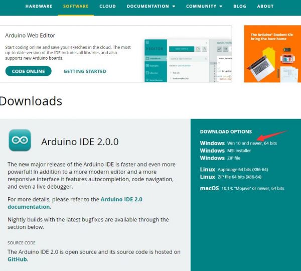
  1. Just click on "JUST DOWNLOAD".

  2. Click to install after downloading.

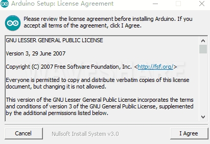
  3. Note: You will be prompted to install the driver during the installation process, we can click Install.

Install Arduino-Pico Core on Arduino IDE

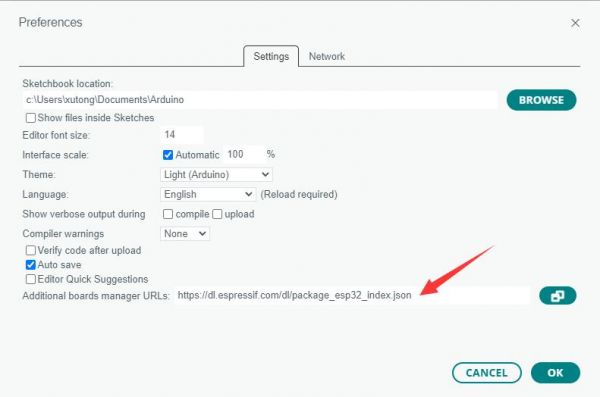
  1. Open Arduino IDE, click the File on the left corner and choose "Preferences".

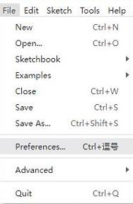
  2. Add the following link in "Additional boards manager URLs", then click OK.

    https://github.com/earlephilhower/arduino-pico/releases/download/global/package_rp2040_index.json

    Note: If you already have the ESP32 board URL, you can separate the URLs with commas like this:

    https://dl.espressif.com/dl/package_esp32_index.json,https://github.com/earlephilhower/arduino-pico/releases/download/global/package_rp2040_index.json
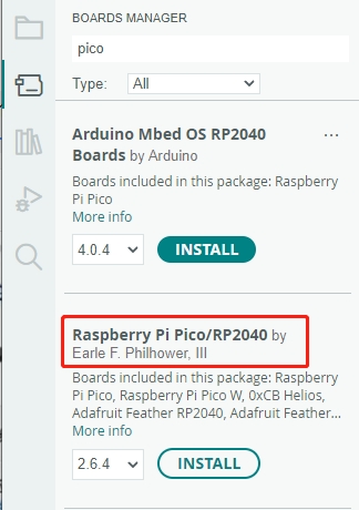
  3. Click on Tools -> Board -> Board Manager -> Search for pico, it shows installed since my computer has already installed it.

Upload Demo At the First Time

  1. Press and hold the BOOTSET button on the Pico board, connect the Pico to the USB port of the computer via the Micro USB cable, and release the button when the computer recognizes a removable hard drive (RPI-RP2).

  2. Download the demo, open the D1-LED.ino under arduino\PWM\D1-LED path.

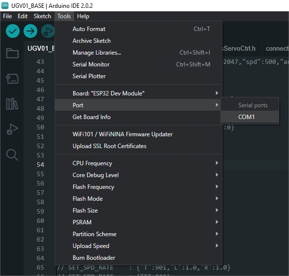
  3. Click Tools -> Port, remember the existing COM, do not need to click this COM (different computers show different COM, remember the existing COM on your computer).

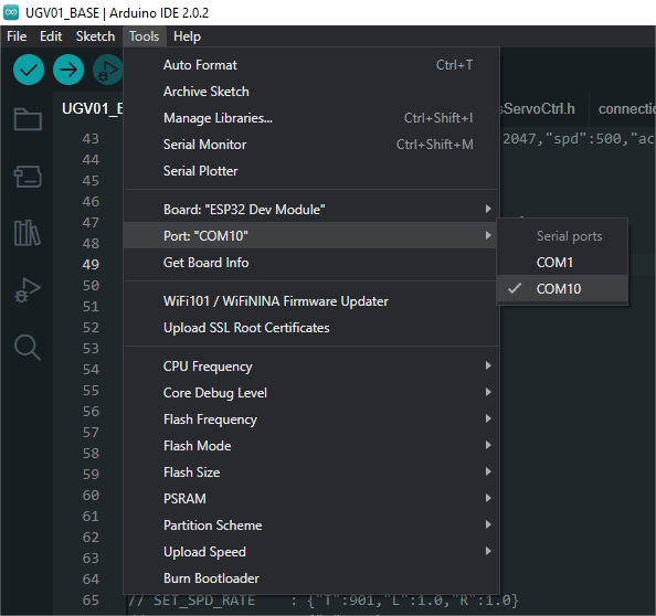
  4. Connect the driver board to the computer with a USB cable, then click Tools -> Ports, select uf2 Board for the first connection, and after the upload is complete, connecting again will result in an additional COM port.

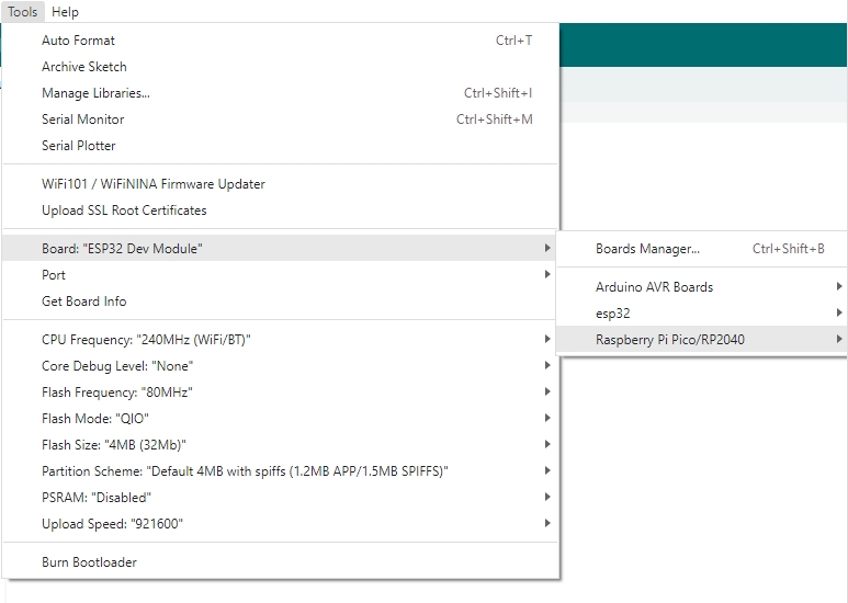
  5. Click Tools -> Board -> Raspberry Pi Pico/RP2040 -> Raspberry Pi Pico.

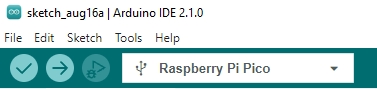
  6. After setting, click the right arrow to upload.

    • If you encounter problems during the period, you need to reinstall or replace the Arduino IDE version, uninstall the Arduino IDE clean, after uninstalling the software you need to manually delete all the contents of the folder C:\Users\[name]\AppData\Local\Arduino15 (you need to show the hidden files in order to see it) and then reinstall.

Open Source Demo

Download the Arduino IDE installation package from .

Schematic
ESP8266 AT Instruction Set
ESP8266 AT Command example
More...
Demo codes
Thonny Python IDE (Windows V3.3.3)
TCP/UDP Debug software
Flash Download tool
AT firmware
TCP232
Raspberry Pi Pico
【MicroPython】 machine.Pin Function
【MicroPython】 machine.PWM Function
【MicroPython】 machine.ADC Function
【MicroPython】 machine.UART Function
【MicroPython】 machine.I2C Function
【MicroPython】 machine.SPI Function
【MicroPython】 rp2.StateMachine
【C/C++】 Windows Tutorial 1 - Environment Setting
【C/C++】 Windows Tutorial 2 - Create New Project
Arduino website
MicroPython Demo (GitHub)
MicroPython Firmware/Blink Demo (C)
Official Raspberry Pi C/C++ Demo
Official Raspberry Pi MicroPython Demo
Arduino Official C/C++ Demo
LogoWaveshare ESP8266 for Raspberry Pi Pico Wifi Module TCP UDPOpenELAB