Waveshare MAX-M8Q GNSS HAT for Raspberry Pi
Product Link
Positioning Principle
What's GNSS
GNSS (Global Navigation Satellite System) is a general term for multiple satellite systems. At present, there are BDS (China), GLONASS (Russia), GPS (United States), Galileo (Europe), QZSS (Japan) and IRNSS (India) navigation satellite systems in the world. The features of GNSS are as follows:
GPS is widely used with mature technology, and the frequency band signals such as L1C/A, L2C and L5, have improved the positioning accuracy.
GNSS modules with multi-system and multi-band can capture satellites from different satellite systems, which greatly increases the number of effective satellites and improves positioning accuracy and stability.
The signal received by the GNSS module contains reflected and refracted signals, resulting in multi-path effects that affect the positioning accuracy. The multi-band and multi-constellation system technology can effectively lessen errors caused by the atmosphere and improve positioning accuracy.
With the development of GNSS, a variety of positioning technologies such as RTK, PPP-RTK and multi-sensor fusion positioning DR (Dead Reckoning) have emerged to meet the needs of differentiated high-precision positioning.
GPS Principle
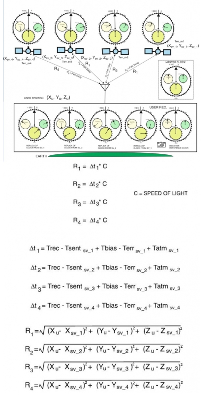
In this section, the working principle of GPS receiver positioning is shown in the figure below, and the details are described in the following 5 points. For details of the positioning principle, please refer to GPS Positioning Principle, GPS Operation Principle, Fundamentals of gps receivers and FUNDAMENTALS OF GPS.
GPS satellites continuously send radio signals with their own time and position information in the air for GPS receivers (GNSS modules such as ZED-F9P)
A pseudo-random code will be generated inside the satellite and the receiver. Once the two pseudo-random codes are synchronized, the receiver can measure the difference between the time the radio signal is transmitted and the time it arrives at the receiver (referred to as the time delay), and multiply the time delay by the speed of light to get the distance (pseudorange).
The time of the GPS system is maintained by the rubidium atomic frequency standard of the atomic clocks on each satellite. These satellite clocks are generally accurate to within a few nanoseconds of Coordinated Universal Time (UTC), which is maintained by the Naval Observatory's "Master Clock", the stability of each master clock is several 10^(-13) seconds.
Computers and navigation information generators on GPS satellites know precisely their orbital positions and system time, while a global network of monitoring stations keeps track of satellites' orbital positions and system time. The main control station at Schriever Air Force Base in Colorado, together with its operation and control section, input the orbital position and onboard clock correction data calculated on the basis of complex models into each GPS satellite at least once a day.
To calculate the 3D position of the GPS receiver (GNSS module), the GPS receiver is required to receive signals from at least four satellites, and the 3D position is calculated according to the space triangle Pythagorean theorem and the quadratic linear equation.
What's RTK
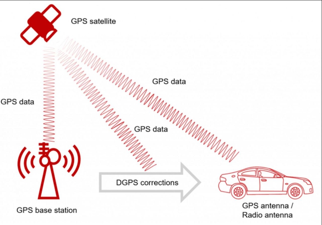
RTK (Real Time Kinematic), also known as carrier phase differential technology, is a GNSS positioning technology that supports centimeter-level positioning accuracy (referred to as RTK) and is a differential method for real-time processing of the carrier phase observations of two measuring stations. The working process of RTK is shown in the figure below. The DGPS corrections generated by the base station (GNSS receiver) are transmitted to the mobile station (GNSS receiver) in real-time through the mobile network for calculation and centimeter positioning.
RTK Application
Apply in various control surveys such as traditional geodetic surveys and engineering control surveys in triangulation and wire netting methods, and use RTK to measure the positioning accuracy in real-time to ensure observation quality and improve operational efficiency. Compared with non-real-time measurements such as normal GPS static surveys, fast static surveys, and pseudo-dynamic surveys, it must be retested when the accuracy does not meet the requirements. In addition, RTK is used in highway control measurement, electronic circuit control measurement, water conservancy engineering control measurement, and geodetic survey, which can reduce labor intensity, save costs, and complete control point measurement within minutes or even seconds.
Topographic mapping: Using RTK only requires one person with the instrument to stay at the detail point for a second or two, and input the feature code at the same time. The accuracy of points and areas can be known in real-time through the handbook. After returning to the room, the professional software interface can output the required topographic map. In this way, RTK only requires one person to operate, and it does not require point-to-point vision, which greatly improves efficiency. With RTK and the electronic handbook, you can measure and design various topographic maps, such as general surveying, railway strip topographic maps, highway pipeline topographical maps, reservoir topographic maps, nautical ocean surveying, and so on with the depth sounder.
Setting out is an application branch of measurement. When using RTK to set out, you only need to input the designed point coordinates into the electronic handbook with the GPS receiver on your back, and it will remind you to go to the position. It is not only fast and easy but also is high-accuracy and uniform as GPS is set out by coordinates directly. Hence, the efficiency of setting out in exterior operation is greatly improved, and only one person to operate.
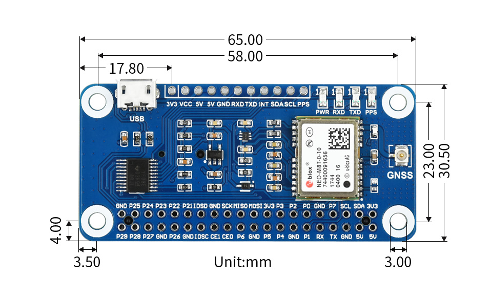
Dimension
Test it in Windows PC
1. Download and install u-center software and then enter it. 2. Set the jumpers in the A area, assemble the GNSS antenna, and set the receiver of the antenna on the open area outside. Connect it to the micro USB interface and the PC. 3. Note that you should set the side without sticker upward, Open Device Manager and view the COM port, connect MAX-M8Q, and use auto-baudrate. 4. Power the MAX-M8Q module and set it to 3D mode, select File -> Database Export -> Google Map Html to export file. 5. Download Test file, unzip and open it by Chrome browser, and import the file which is saved from u-center above to check position information. 6. Please refer to the User guide about how to use the u-center.


Using with Raspberry Pi
Hardware Connection

5V
-
-
5V Power input
GND
-
-
Ground
RXD
P14
P15
Receiver pin of UART
TXD
P15
P16
Transmit pin of UART
SDA
P2
P8
SDA pin of I2C
SCL
P3
P9
SCL pin of I2C
PPS
P18
P1
PPS pin of module
INT
P27
P2
Wakeup pin, low active
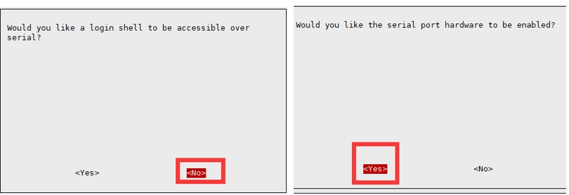
Enable Serial Port
Open the Raspberry Pi Terminal and configure by commands.
Install and Modify Parameters
Install the Python library function:
Modify gpsd:
Download demo codes:
Python Example
Enter the python directory (demo codes), and run the example.

NTP Server
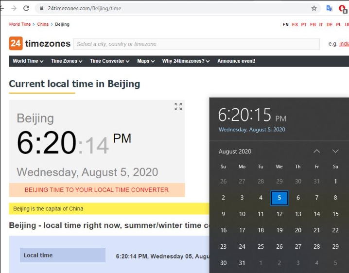
The system clock of personal computers, servers, and other equipment will be skewed as shown in the figure below. High-precision clock scenarios will be affected in high-frequency trading systems, automated production lines, etc., while NEO-M8T can achieve coverage in harsh signal environments. It relies on the atomic clock on the satellite to ensure that the accuracy of the clock is not affected by factors such as the network. In this section, NEO-M8T and Raspberry Pi are used to build an NTP server to provide timing functions for devices in the local area network in an indoor closed environment.
1. Connect the NEO-M8T GNSS TIMING HAT to the antenna, and place the other end of the antenna near the outer wall or window sill. 2. Connect the NEO-M8T connected to the antenna to the Raspberry Pi, power it on, and wait for the NE0-M8T to output the PPS signal. 3. Copy and paste the following command to the Raspberry Pi command line to execute.
4. The installation takes a long time, reboot the Raspberry Pi after installation. 5. Open the /boot/config.txt file, jump to the last line, change gpiopin=4 to gpiopin=18, press Ctrl+X then Y and press Enter to save.
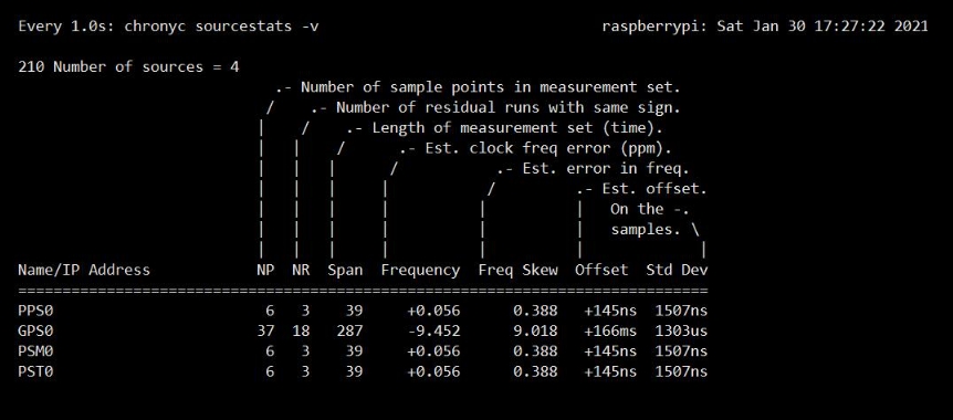
6. Use the following command to test the operation of pps0, the Raspberry Pi time has already used the time system provided by NEO-M8T
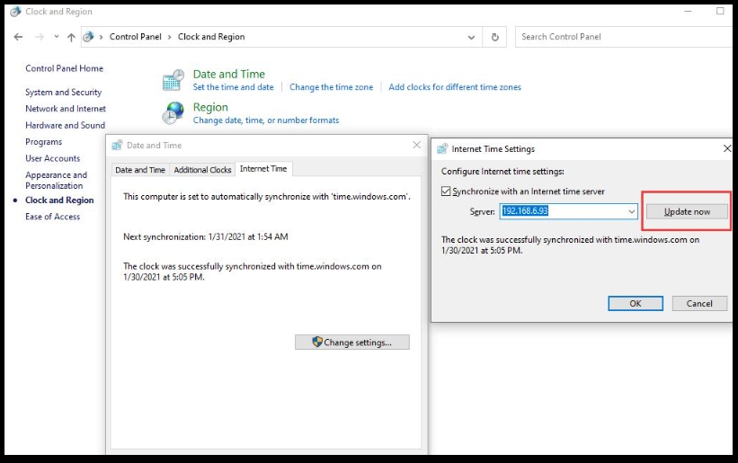
7.To provide time for other devices, obtain the address of the Raspberry Pi running NTP, such as 192.168.6.93.
8. For Linux devices, use the following command to synchronize the time.
Using STM32 Board
Hardware Connection

5V
-
5V Power input
GND
GND
Ground
RXD
P9(TX)
Receive pin of UART
TXD
P10(RX)
Transmit pin of UART
Run the example
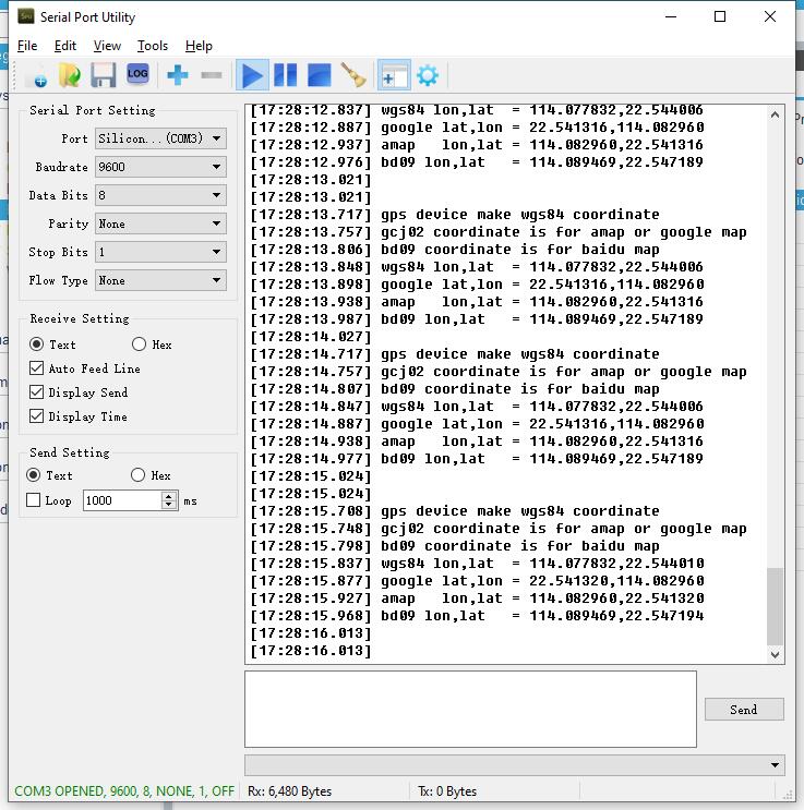
Download the demo codes. Open the STM32 project by Keil software, compile and download it to the XNUCLEO-F103RB board, connect UART2 pins to the PC, and check the information with COM assistance software.
Using with Jetson Nano
Install Python library function:
Modify gpsd parameters:
Download the demo:
Check the port for data:
python
Enter the python directory and run the demo, and you can view the information directly on Google Maps.

Resources
Documents
Demo codes
Software
Datasheet
FAQ
Last updated
Was this helpful?

