Waveshare RM500U-CNV Raspberry PI 5G/4G/3G Hat
Product Link
Features
Integrates extensive network protocols, with multi drivers and software support, compatible with different OS including Windows / Linux / Android.
USB 3.1 port (USB 2.0 compatible) for connecting to PC, Raspberry Pi, or Jetson Nano host board to enable high-speed 5G communication.
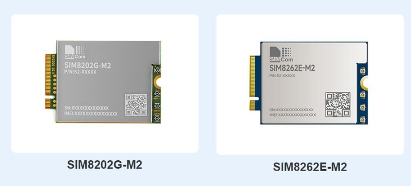
Standard M.2 B KEY slot, compatible with different 5G modules: RM500U-CN / RM500Q-GL / RM500Q-AE / RM502Q-AE series.
Onboard UART, PWR, and RST control pin, built-in voltage level translator, enabled via DIP switch, for use with hosts like Raspberry Pi or Arduino.
Onboard USB-C connector, enabled via a switch, for connecting the standalone power supply for the module, allows more loads, a stable and flexible power supply.
Onboard power supply on/off switch, reset button, and LED indicator, easy to turn on/off the module or monitor the operating status.
2 x SIM card slot, dual card single standby, switchable via AT command. (Some 4G/5G modules do not support dual sim cards, depending on the actual supporting modules.)
High-efficiency power supply circuit, up to 3A output current.
Version Options
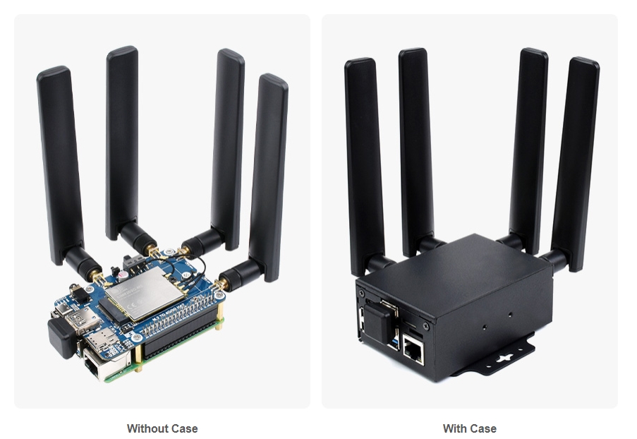
This product is available with an optional 5G module and also with the optional case.
Selection Guide
Picture


5G Standard
3GPP R15
3GPP R16
5G Chip
UNISOC
Qualcomm
5G
Sub-6 GHz
Sub-6 GHz & mmWave
Region/Operator
China, EMEA, Asia-Pacific
except Americas
except China
Global
Operating Temperature
-30°C ~ +75°C
Extension Temperature
-40°C ~ +85°C
Module Size
30.0 × 52.0 × 2.3 (mm)
Module Weight
8.8g
8.7g
8.8g
Power Supply
3.3~4.4V, Typ. 3.7V
3.135~4.4V, Typ. 3.7V
Power Consumption
78μA @ shutdown;
5.1mA @ hibernate; 57mA @ USB 2.0, idle; 71mA @ USB 3.0, idle
70μA @ shutdown;
4.0mA @ hibernate; 32mA @ USB 2.0, idle; 54mA @ USB 3.0, idle
80μA @ shutdown;
4.2mA @ hibernate; 39mA @ USB 2.0, idle; 54.5mA @ USB 3.0, idle
195μA @ shutdown;
4.7mA @ hibernate; 41mA @ USB 2.0, idle; 60mA @ USB 3.0, idle
173μA @ shutdown;
5.1mA @ hibernate; 51mA @ USB 2.0, idle; 69mA @ USB 3.0, idle
Frequency Band
5G
5G NR
-
n257, n258, n260, n261
5G NR NSA
n41, n78, n79
n41, n77, n78, n79
n1, n2, n3, n5, n7, n8, n12, n20, n25, n28, n38, n40, n41, n48, n66, n71, n77, n78, n79
n1, n2, n3, n5, n7, n8, n12, n13, n14, n18, n20, n25, n26, n28, n29, n30, n38, n40, n41, n48, n66, n70, n71, n75, n76, n77, n78, n79
5G NR SA
n1, n2, n3, n5, n8, n28, n41, n77, n78, n79
n1, n2, n3, n5, n7, n8, n12, n20, n25, n28, n38, n40, n41, n48, n66, n71, n77, n78, n79
n1, n2, n3, n5, n7, n8, n12, n13, n14, n18, n20, n25, n26, n28, n29, n30, n38, n40, n41, n48, n66, n70, n71, n75, n76, n77, n78, n79
LTE
LTE-FDD
B1, B3, B5, B8
B1, B2, B3, B4, B5, B7, B8, B12, B13, B14, B17, B18, B19, B20, B25, B26, B28, B29, B30, B32, B66, B71
LTE-TDD
B34, B38, B39, B40, B41
B34, B38, B39, B40, B41, B42, B43, B48
LAA
-
B46
UMTS
WCDMA
B1, B5, B8
B1, B2, B3, B4, B5, B6, B8, B19
B1, B2, B4, B5, B8, B19
GNSS
-
GPS / GLONASS / BeiDou(Compass) / Galileo / QZSS (only RM520N-GL and RM530N-GL support)
Data Rate
5G mmWave
-
DL 4.0Gbps; UL 1.4Gbps
5G SA Sub-6
DL 2Gbps; UL 1Gbps
DL 2.1Gbps; UL 900Mbps
DL 4.2Gbps; UL 450Mbps
DL 2.4Gbps; UL 900Mbps
5G NSA Sub-6
DL 2.2Gbps; UL 575Mbps
DL 2.5Gbps; UL 600/650Mbps
DL 5Gbps; UL 650Mbps
DL 3.4Gbps; UL 550Mbps
LTE
DL 600Mbps; UL 150Mbps
DL 1.0Gbps; UL 200Mbps
DL 2Gbps; UL 200Mbps
DL 1.6Gbps; UL 200Mbps
UMTS
DL 42.2Mbps; UL 11Mbps
DL 42Mbps; UL 5.76Mbps
What's On Board

①
Raspberry Pi GPIO Header
Easily connect to Raspberry Pi
②
Switch
Enable the corresponding pin
③
M.2 Interface
Compatible with RM500U-CN/RM500Q-CN/RM500Q-GL/RM50XQ-AE and other series of 5G modules
④
SIM Card Holder
Onboard two SIM card slots, dual card single standby. The default SIM1 card slot works, SIM2 is on the back, requires module support and must be switched through AT commands
⑤
USB 3.1 Connector
Backward compatible with USB 2.0, can be used to connect to PC/Raspberry Pi/Jetson Nano, etc.
⑥
USB Type-C Connector
5V 3A input; stable and flexible power supply
⑦
Audio Port
SIM82XX series support audio function, RM50XX series do not support this audio function
⑧
Antenna Connector
Onboard four-way antenna, strong signal
⑨
Reset Switch
One-key reset
⑩
Power Switch
To facilitate the power supply mode of the control module:
——If set to USB, the module will provide power through the "⑤.USB3.1 interface"; ——If set to EXT PWR, the module will provide power through the "⑥.USB Type-C interface" external power supply
⑪
Cooling Fan
Cool down the Raspberry Pi and 5G module at the same time
⑫
Indicator
Check the module running status anytime, anywhere

⑬
Cooling Fan
Simultaneously cooling Raspberry Pi and 5G modules
⑭
SIM Card Slot 2
Switchable via AT command (module is required)
⑮
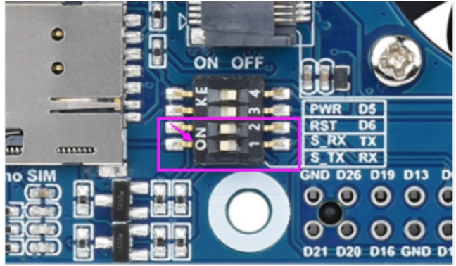
Module Setting Switch
Switch A to ON for SIM7600X/A7906X/IM7906X/SIM7912X series 4G M.2 module; Switch B to ON, for SIM8202X/SIM8200EA/SIM8262X series 5G M.2 module; Switch C to ON, for RM50X/RM520N-GL/EM06X series 5G/LTE-A M.2 module
⑯
USB Interface Pad
USB 2.0 interface pad
⑰
NAU8810X Audio Chip
For SIMN7600X/SIM8XXX series module, does support RM5XX and EM06XX series module
⑱
Fan Header
5V power supply for cooling fan
Pinout Definition
After connecting to Raspberry Pi, these pins (TX, RX, D4 and D6) can be connected or not through the DIP switch:

4G/5G modules function testing
Category
4G/5G Module
Network Communication
GNSS Positioning
Voice calls through Earphone Port
Dual SIMs
UART Interface
External Power Supply?
5G
SIM8202G-M2
5G/4G/3G
Support
Support
Support
Support
Optional, but recommended
5G
SIM8200EA-M2
5G/4G/3G
Support
Support
Support
Support
Optional, but recommended
5G
RM500U-CN
5G/4G/3G
NOT Support
NOT Support
Support
Support
Recommended
5G
RM500Q-GL
5G/4G/3G
Support
NOT Support
Support
NOT Support
Recommended
5G
RM500Q-AE
5G/4G/3G
Support
NOT Support
NOT Support
NOT Support
Recommended
5G
RM502Q-AE
5G/4G/3G
Support
NOT Support
NOT Support
NOT Support
Recommended
LTE-A
EM06-E
LTE-A/4G/3G
NOT Support
NOT Support
NOT Support
NOT Support
Optional
LTE-A
A7906E
LTE-A/4G/3G
NOT Support
NOT Support
NOT Support
NOT Support
Optional
4G
SIM7600G-H-M2
4G/3G/2G
Support
Support
NOT Support
Support
Optional
4G/5G Module Compatibility
If you need to use the M.2 TO 4G/5G HAT for other 4G/5G modules, you can refer to the M.2 connection diagram below, check whether there is any pin conflict, and then connect to test:

Working With Windows
Install Drivers
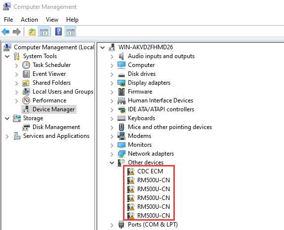
After connecting the RM500U-CN 5G HAT to the computer through a double-ended usb3.0 data cable, there will be a series of devices without drivers installed on other devices:
Download the driver to your computer and unzip the compressed package.
Enter the RM500U_Driver directory.
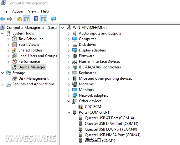
Click setup.exe to install the driver. After the installation is complete, the device manager will generate the following devices:
Common AT Commands
EM25X, EM06E and RM50X series 4G/5G module support AT command control, some basic AT commands are shown in the table below:

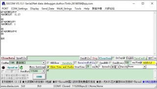
SSCOM串口助手AT指令收发实测
AT
AT Test Command
OK
ATE
ATE1 sets echo ATE0 turns off echo
OK
AT+CGMI
Query module manufactor
OK
AT+CGMM
Query module model
OK
AT+CGSN
Query product serial number (IMEI)
OK
AT+CSUB
Query module version and chip
OK
AT+QGMR
Query firmware version serial number
OK
AT+IPR?
Set module hardware serial port baudrate
+IPR: OK
AT+CFUN=1,1
Reset module
OK
AT+QUIMSLOT?
Query SIM card selection: Return 1, select SIM card 1; Return 2, select SIM card 2
+QUIMSLOT: 1/2 OK
AT+CPIN?
Query SIM card status, return READY, SIM card can normally identify
+CPIN: READY
AT+COPS?
Query the current operator, after normally connecting to the network, it will return the operator's information
+COPS: OK
AT+CEREG?
Query the network registration status
+CEREG: OK
AT+C5GREG?
Query 5G network registration status
+C5GREG: OK
AT+QENG="servingcell"
Query UE system information
AT+QNWPREFCFG="mode_pref",AUTO
Auto-network mode
OK
AT+QNWPREFCFG="mode_pref",NR5G
Prioritize 5G network
OK
AT+QNWPREFCFG="nr5g_band",79
Fixed N79 frequency band
OK
AT+QNWPREFCFG="mode_pref",LTE
Prioritize 4G network
OK
SIM Card Selection
Dual SIM Card Switching
The 5G HAT has two SIM card slots onboard, a dual SIM card, and single standby, which can be switched and enabled by AT command.
SIM card 1 is selected by default, You can use the following command to query and confirm:
To switch SIM card 2, please use the following command:
Switch back to SIM card 1, please use the following command:
Check whether the corresponding card slot recognizes the SIM card:
RM500U-CN and RM500Q-GL support Dual SIMs, but RM500Q-AE and RM502Q-AE modules do not support dual SIM cards.
Windows System
RM500U-CNV MBIM Dial-up Network Access
RNDIS Dial-up Internet Access
Open the RM50X AT port and send the following commands to dial up the Internet:
And then you can find that there are some unrecognized devices in the Device Manager on the computer, such as RNDIS (with an exclamation mark).
Right-click the 'RNDIS', search "Update Divers" and select "Let me pick from a list of available drivers on my computer", then select "Network adapters" from the device list.
Select "Microsoft" in the manufacturer list of the Network adapters window, and then select "Remote NDIS Compatible Device" in the list on the right, which is the remote NDIS compatible device.
Click 'Next' and wait for the installation to finish, the RNDIS Kitl device will be installed successfully.


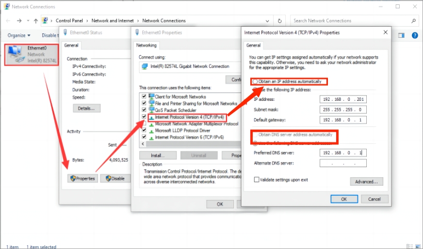
If it cannot connect to the network, please set it to obtain the IP automatically.
Network Speed Test
RM50XQ Network Speed Test
Install speed testing software, such as Internet speed manager and other speed testing software, you can choose to download the speed test at www.speedtest.cn/pc/download.
About the speed testing
As there will be many inconsistencies between actual and laboratory conditions that will result in 5G speeds that are not ideally stable at 100MBPS, there are the following.
Base station distance, the closer to the 5G base station the better the signal and the faster the speed.
Base station load, the fewer people using it the faster it will be, and the slower it will be during peak commuting periods.
Number of base stations: due to the spectrum, an equal amount of 4G coverage requires double the number of 5G base stations.
Operator: you need to confirm your 5G card, and whether the speed is limited, you can regularly ask the operator to reset your network.
Indoor is worse than outdoor: building penetration attenuation, and indoor bypass attenuation.
PS: The current number of base stations still does not have good coverage, and the speed measurement is not quite the same in different locations.
Working with Raspberry Pi
RM500U is based on the Zhanrui platform, and the dial-up Internet access in the Raspbian system of the Raspberry Pi is unstable; it is recommended to use Openwrt, Ubuntu and other mainstream Linux systems.
Ubuntu System Use
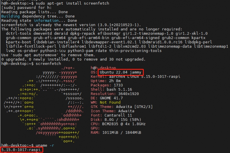
Raspberry Pi programming Ubuntu 22.04 system image.
Confirm system version information:
The USB device descriptor needs to be loaded for the first use
In order to identify a module, the module's VID and PID needs to be added to the file [kernel].
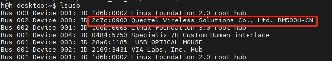
Check the VID and PID of RM500U.
Install gcc and make tools
Add VID and PID:
ECM Dial-up
Open minicom:
Send the following commands in minicom for ECM dialing:
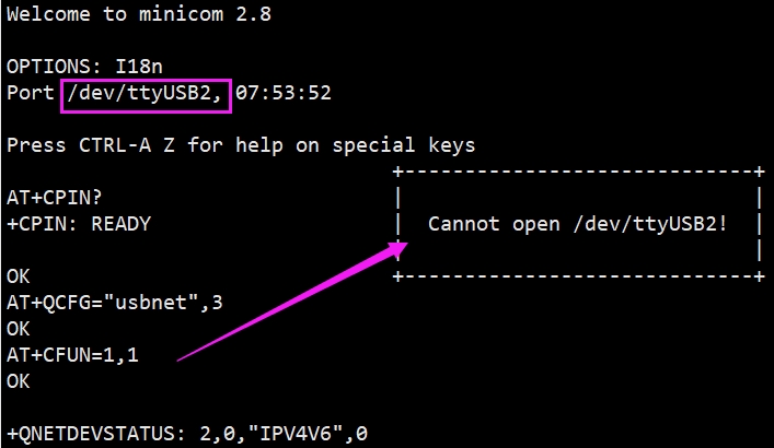
After configuring the ECM mode, CTRL+A -> X -> Yes to exit minicom.
Use the following commands to get IP and set DNS:
After dialing, the Raspberry Pi can see that enxe2f1fbfdd5e7 has obtained the IP through the following command (different systems are different, so the actual obtained IP shall prevail):
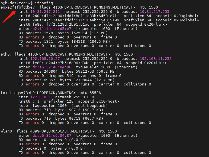
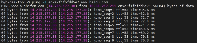
Test enxe2f1fbfdd5e7 network status:
Working with Raspbian System
Add VID & PID
After successfully adding the PID and restarting the Raspberry Pi, enter the following command in the command line interface, and five device descriptors USB0-UBS4 will appear:
RNDIS Dial-up Internet
Open minicom.
Send the following command RNDIS dial in minicom:
If the IP is not obtained or the network is not connected, you can use the following commands to get it:
Raspberry Pi Serial Port Enable
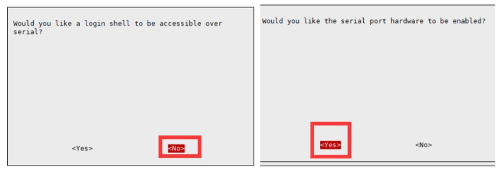
Since the Raspberry Pi serial port is used for terminal debugging by default, if you need to use the serial port, you need to modify the Raspberry Pi settings. Execute the following command to enter the Raspberry Pi configuration:
Select Interfacing Options ->Serial ->NO ->YES to disable serial debugging. Open the /boot/config.txt file, and find the following configuration statement to enable the serial port, if not, add it at the end of the file:
Restart to take effect:
1. Insert the module into the Raspberry Pi, and turn the S_TX and S_RX of the DIP switch to ON: 2. Install minicom, minicom is a serial debugging tool for the Linux platform:
3. Open ttyS0 through minicom——ttyS0 is the serial port of Raspberry Pi 3B/3B+/4B, the default baud rate is 115200;
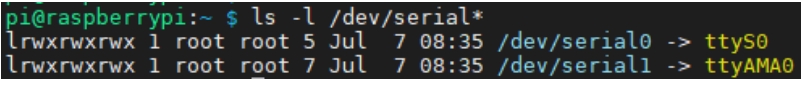
4. For Raspberry Pi 2B/zero, the user serial device number is ttyAMA0; you can use the following command line to confirm, serial0 is the selected serial device number, as shown below:
OpenWrt
Introduction
Soft routing is using desktops or servers and other equipment with software. It mainly depends on the settings of the software to achieve the functions of the router. The hard routing is a unique hardware device, including a processor, power supply, and embedded software to provide router functionality. OpenWrt is a very popular soft routing system. It is a highly modular and highly automated embedded Linux system with powerful network components and scalability. It is often used in industrial control equipment, routers, and other equipment. In addition to the functions of general home routers, OpenWrt soft routing can also achieve port forwarding, intranet penetration, 4G networking, FTP server, and more powerful functions.
Burn the image
Download the RPI OpenWrt system, unzip the system in the Imgs directory, and use the burning tool to burn the system to the SD card.
Login and initial settings
After the OpenWrt system is turned on, the Raspberry Pi is equivalent to a router. Therefore, use a network cable to connect the Raspberry Pi to the computer according to the use of the router (you can also use the mobile phone to search for WIFI, the default name is "OpenWrt").
You can set the language to auto first.

Enter 192.168.1.1 on the web page, the default user name: root, and the default password: password, enter the OpenWrt web management interface.

Set WIFI password: Network —> Wireless —> interface configuration —> Wireless security.

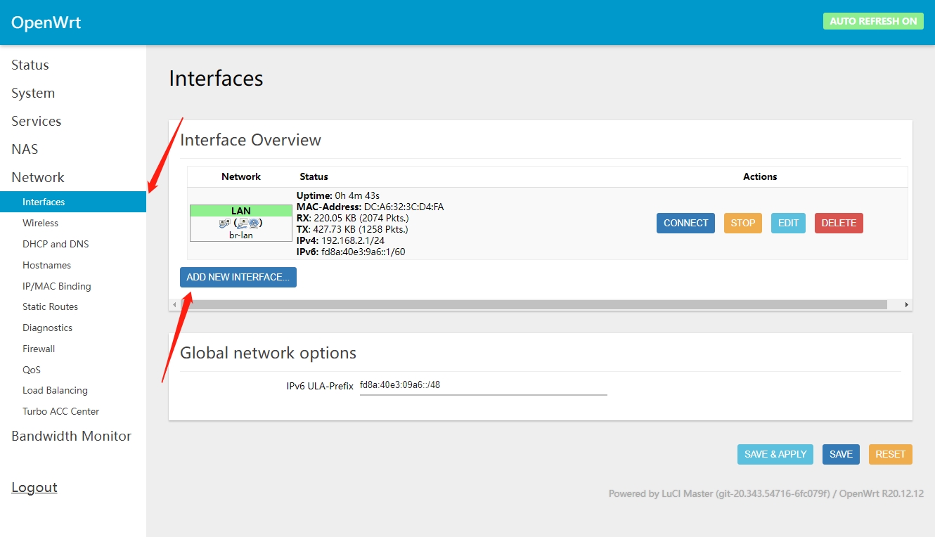
Create the new interface: Network -> Interface -> Create interface.
Modify the IPv4 address of the LAN port to a different IP that is not the same as the LAN port IP of other routers in your home. (Many routers default the LAN port IP to 192.168.1.1. If you do not modify the IP of the OpenWrt, it will easily lead to conflicts and failure to connect to the Internet).
If necessary, it is also recommended to disable the IPv6 allocation length. After the modification is completed, click "Save & Apply", and re-use 192.168.10.1 to access the OpenWrt console.

In addition, it is recommended to adjust the Firewall setting to connect the OpenWrt terminal and Web management interface through the local area.
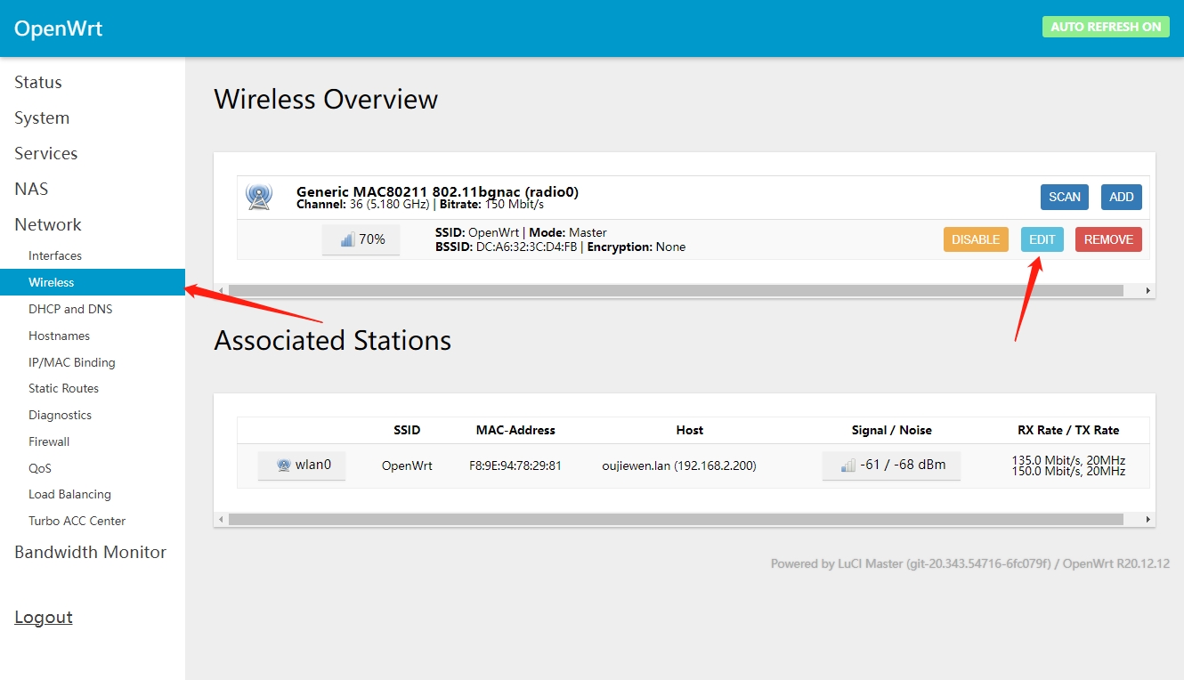
Network —> Firewall, change all "reject" to "accept", and click "Save & Apply" after modification, as shown in the picture below:

And then select System -> Administration, modify the allowed interface for SSH access to "unspecified" (that is, any interface can be accessed by ssh), check the Gateway port, and click "Save & Apply" after the modification is completed.

At this point, you can connect to the OpenWrt web management interface or terminal through the IP address of the LAN port or wan port.
Configure networking
Insert the SIM card into the slot of the communication module -> All 5G antennas are connected, after connecting to the Raspberry Pi 4B via USB -> Power on;
Change the mobile communication module to RNDIS mode (USB network sharing mode), which can be changed in Openwrt by sending the following command via minicom:
To switch ECM mode, use this command:
Add new interface: Network -> Interfaces -> Add New Interface.
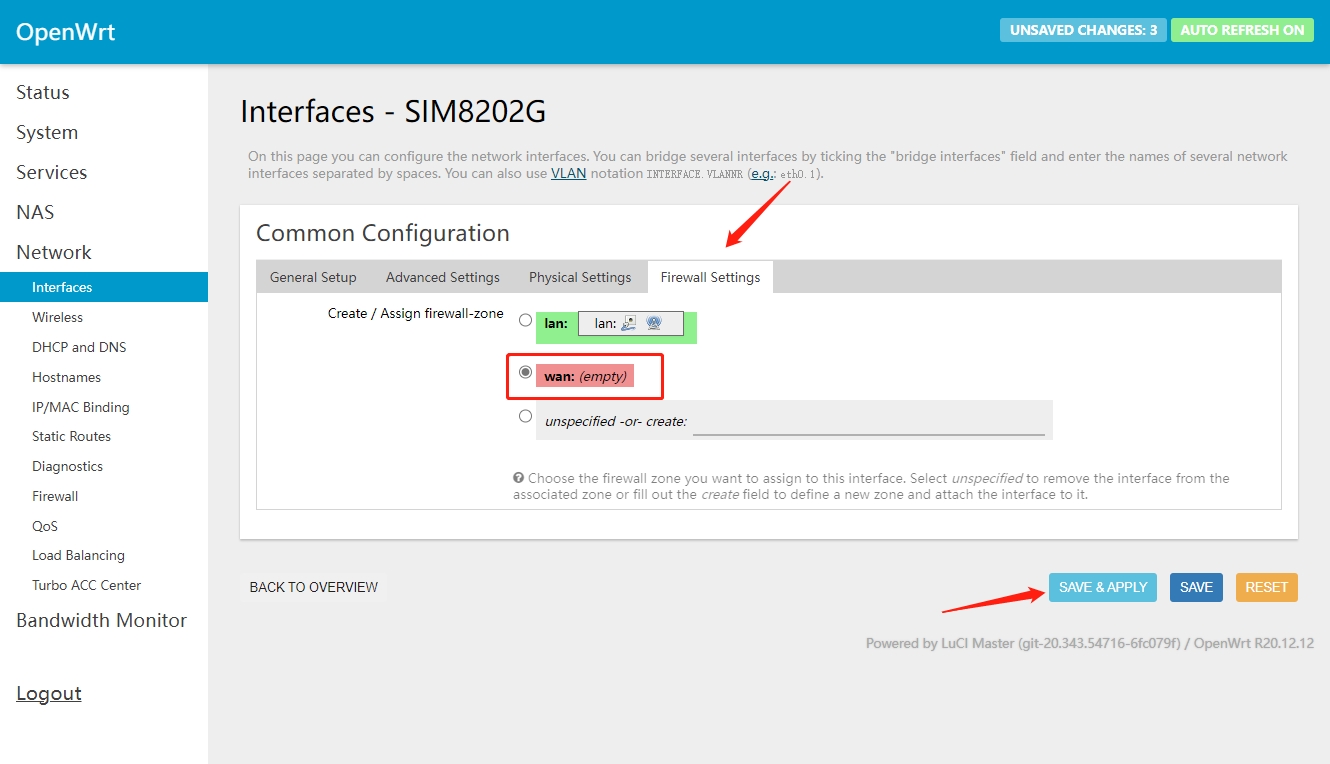
Create new interface: name of new interface - SIM8202G; protocol of new interface - DHCP client; include the following interfaces - ethernet adapter: "usb0"; submit.

Configuration interface: Firewall settings - wan; save & apply.
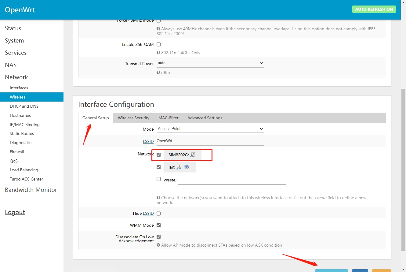
Wireless configuration: Network -> Wireless -> Modify -> Interface Configuration -> Basic Settings -> Check SIM8202G (Defined by yourself) and lan in Network; Save & Apply.
Working with Jetson Nano
Hardware Connection
Connect the RM500U-CN with a double-ended usb3.0 data cable, and connect an external 5V power supply to the Type-C power supply port of the RM500U-CN 5G HAT, as shown in the figure:

Load USB Device Descriptor
In order to identify the module, the module's VID and PID information needs to be added to the file [kernel].
View VID and PID of RM500U:
 Added VID sum PID
Please do not delete or modify the four directory files of option directory, default.script and install.sh, otherwise it will affect the loading of device descriptors!
After successfully adding the PID and restarting Jetson nano, enter the following command in the command line interface to display five device symbols USB0-USB4.

RNDIS
Enable minicom.
Send the following command ECM in minicom.
After the module restarts and the NET light is on, use the following command to check the network status (optional).

Get the IP and set the DNS with the following commands:
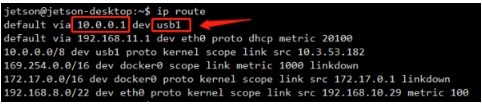
After dialing, you can see that usb1 gets the IP through the following command:
Test usb1 networking status.

Resources
Program
Assembly drawing
Software
Datasheet
Related Application Cases
FAQ
What if it powers off?
As the 5G power consumption is relatively high, and the host computer's USB port may not be able to provide it with sufficient power, please refer to the USB dual plug cable to provide the module with sufficient power, as shown in the figure:

How to switch the card slot?
RM500U-CN and RM500Q-GL modules support installing two SIM cards at the same time, and you can enable one SIM card to work with AT commands:

If the corresponding SIM card can not be identified, it may because the DIP switch has not enable the corresponding module, please make the DIP switch corresponding to C turn on:

What can I do when the NET indicator is not on and the network is not registered?
Please check whether the SIM card is connected to four antennas.
Please check hardware connection is right and check the network with the following AT Log:

How to confirm whether the Raspberry Pi hardware serial port is ttyS0 or ttyAMA0?
Raspberry PI 2B/zero, the user serial port device number is ttyAMA0;
The following command line can be used to confirm that serial0 is the serial port device number selected, as shown in the figure below:

Why does the USB power supply fail to power off when the computer is used, but the power goes off when the Raspberry Pi is used, and the NET light does not light up for a while?
The USB power supply capability of the Raspberry Pi is worse than that of the computer. It needs to be connected to an external power supply. Please set the switch to EXT PWR, and connect the HAT interface to a 5V 3A power supply:

Last updated
Was this helpful?