Waveshare SIM7600G-H M.2 4G HAT for Raspberry Pi 4G/3G/2G GNSS
Product Link
Introduction
Prohibited by the module manufacturer SIMCOM, we're not allowed to ship this product or to provide any tech support, to the following countries/regions: Iran, North Korea, Cuba, Sudan, and Syrian. SIM7600G-H M.2 4G HAT For Raspberry Pi, LTE CAT4 High Speed, Global Coverage Multi-Band, 4G/3G/2G Compatible, GNSS

Features
Supports dial-up, phone call, SMS, TCP, UDP, MQTT, HTTP(S), FTP(S), and so on.
GNSS positioning: GPS, Beidou, Glonass, Galileo, QZSS, LBS base station.
USB 3.1 port (USB 2.0 compatible) for connecting to PC, Raspberry Pi, or Jetson Nano host board to enable high speed 4G communication.
Onboard UART, PWR, and RST control pin, built-in voltage level translator, enabled via DIP switch, for use with hosts like Raspberry Pi or Arduino.
Onboard USB-C connector, enabled via switch, for connecting standalone power supply for the module, allows more loads, stable amd flexible power supply.
Onboard power supply on/off switch, reset button and LED indicator, easy to turn on/off the module or monitor the operating status.
Reserved 4x SMA to IPEX antenna interfaces, with pre-soldered 2x connectors for easily using antennas, allows changing the SMA antenna position.
Onboard audio jack and audio decoder, allows audio operation like making phone call.
High efficiency power supply circuit, up to 3A output current.
Specifications

①
Raspberry Pi GPIO Header
Easily connect to Raspberry Pi
②
Switch
Enable the corresponding pin
③
M.2 Interface
Compatible with RM500U-CN/RM500Q-CN/RM500Q-GL/RM50XQ-AE and other series of 5G modules
④
SIM Card Holder
Onboard two SIM card slots, dual card single standby. The default SIM1 card slot works, SIM2 is on the back, requires module support and must be switched through AT commands
⑤
USB 3.1 Connector
Backward compatible with USB 2.0, can be used to connect to PC/Raspberry Pi/Jetson Nano, etc.
⑥
USB Type-C Connector
5V 3A input; stable and flexible power supply
⑦
Audio Port
SIM82XX series support audio function, RM50XX series do not support this audio function
⑧
Antenna Connector
Onboard four-way antenna, strong signal
⑨
Reset Switch
One-key reset
⑩
Power Switch
To facilitate the power supply mode of the control module:
——If set to USB, the module will provide power through the "⑤.USB3.1 interface"; ——If set to EXT PWR, the module will provide power through the "⑥.USB Type-C interface" external power supply
⑪
Cooling Fan
Cool down the Raspberry Pi and 5G module at the same time
⑫
Indicator
Check the module running status anytime, anywhere

⑬
Cooling Fan
Simultaneously cooling Raspberry Pi and 5G modules
⑭
SIM Card Slot 2
Switchable via AT command (module is required)
⑮
Module Setting Switch
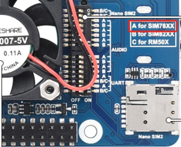
Switch A to ON for SIM7600X/A7906X/IM7906X/SIM7912X series 4G M.2 module; Switch B to ON, for SIM8202X/SIM8200EA/SIM8262X series 5G M.2 module; Switch C to ON, for RM50X/RM520N-GL/EM06X series 5G/LTE-A M.2 module
⑯
USB Interface Pad
USB 2.0 interface pad
⑰
NAU8810X Audio Chip
For SIMN7600X/SIM8XXX series module, does support RM5XX and EM06XX series module
⑱
Fan Header
5V power supply for cooling fan
Pinout
After connecting to Raspberry Pi, these pins (TX, RX, D4 and D6) can be connected or not through the DIP switch:

4G/5G modules function testing
Category
4G/5G Module
Network Communication
GNSS Positioning
Voice calls through Earphone Port
Dual SIMs
UART Interface
External Power Supply?
5G
SIM8202G-M2
5G/4G/3G
Support
Support
Support
Support
Optional, but recommended
5G
SIM8200EA-M2
5G/4G/3G
Support
Support
Support
Support
Optional, but recommended
5G
RM500U-CN
5G/4G/3G
NOT Support
NOT Support
Support
Support
Recommended
5G
RM500Q-GL
5G/4G/3G
Support
NOT Support
Support
NOT Support
Recommended
5G
RM500Q-AE
5G/4G/3G
Support
NOT Support
NOT Support
NOT Support
Recommended
5G
RM502Q-AE
5G/4G/3G
Support
NOT Support
NOT Support
NOT Support
Recommended
LTE-A
EM06-E
LTE-A/4G/3G
NOT Support
NOT Support
NOT Support
NOT Support
Optional
LTE-A
A7906E
LTE-A/4G/3G
NOT Support
NOT Support
NOT Support
NOT Support
Optional
4G
SIM7600G-H-M2
4G/3G/2G
Support
Support
NOT Support
Support
Optional
4G/5G Module Compatibility
If you need to use the M.2 TO 4G/5G HAT for other 4G/5G modules, you can refer to the M.2 connection diagram below, check whether there is any pin conflict, and then connect to test:

How to Use
Dail-up
[Note]: You must use a SIM card with GPRS networking function enabled and not out of service.
NDIS Dail-up
At present, when using Windows 10 operating system, you can connect to 4G DONGLE module (equipped with 4G card of China Mobile/Telecom/Unicom). After installing the driver, most computers will automatically connect to the Internet.
If WINdows cannot access the Internet, you need to manually start NDIS dialing, open SIM7600 AT port, and send the command:
At this point, the NDIS dialing takes effect, and the computer can connect to the network; if the dialing command returns an error, send the following command to set the NDIS dialing mode and then dial again:
RNDIS Dial-Up Internet
In addition, dial-up Internet access using RNDIS is also possible:
After the device installed SIM card and antenna, connect the USB port to computer, then connect the power supply.
Refer to the above to install the USB driver
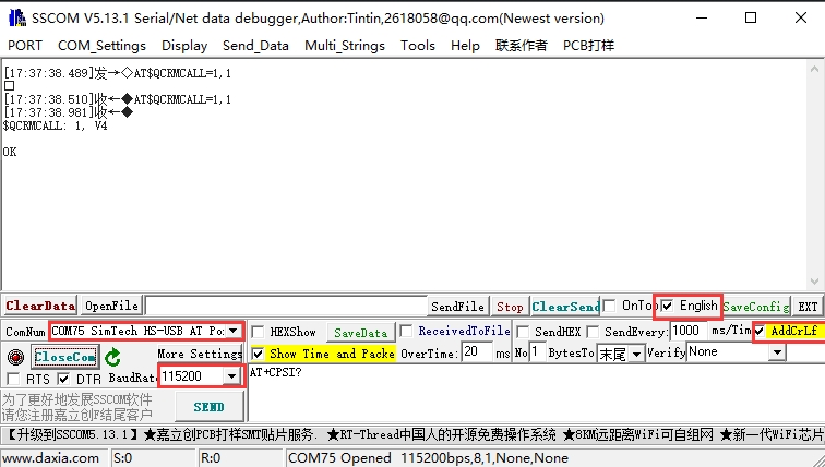
Open the serial port assistant, find the serial port number corresponding to the AT serial port, and send the AT command to check whether it is registered on the network:
If you have successfully registered on the network, then send the AT command to enable USB dial-up Internet access:
If the transmission is successful, the DTU will return OK and reboot automatically.
And then you can find that there are some unrecognized devices in the Device Manager on the computer, such as RNDIS (with exclamation mark).

Right-click the 'RNDIS', search "Update Divers" and select "Let me pick from a list of available drivers on my computer", then select "Network adapters" from the device list.


Select "Microsoft" in the manufacturer list of the Network adapters window, and then select "Remote NDIS Compatible Device" in the list on the right, which is the remote NDIS compatible device.
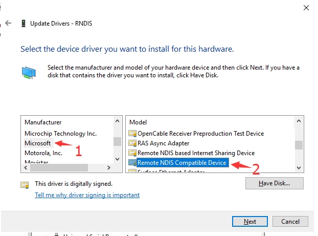
Click 'Next' and wait for the installation to finish, the RNDIS Kitl device will be installed successfully. And then you can see that the PC can access the Internet via DTU.
PPP dial-up
If the NDIS or RNDIS dial-up cannot access the Internet, you can also use PPP dial-up. The operation steps are as follows:
Network and Internet Settings -> Set up a new connection -> Connect to the Internet -> Dial up (D) -> Dial a phone number (D): *99# (others are empty by default) -> Connection -> Register -> Connected to the Internet


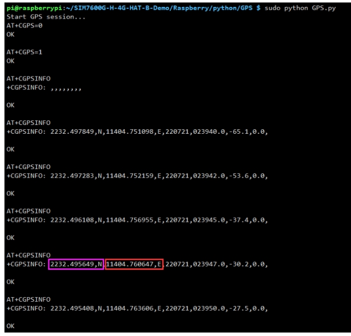
GPS Test
GNSS control instance
Plug in the GPS antenna, and place the receiver tag face down in the open air, (Note that rainy weather cannot be tested) you need to wait about 1 minute before receiving the location signal.

Detailed test instructions and screenshots are as follows:
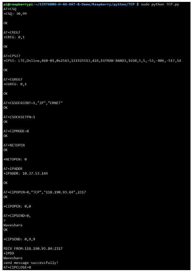
TCP/IP Internet data
GPRS debugging requires a SIM card with the GPRS networking function enabled. The following example takes accessing a mobile SIM card as an example.
Correctly install the mobile phone card (the GPRS networking function must be enabled), the GSM antenna, and connect the USB cable to the computer;
Press the PWR key to start the module and wait for more than ten seconds;
Observe whether the indicator light is normal, the PWR indicator is always on, and the NET indicator is flashing;
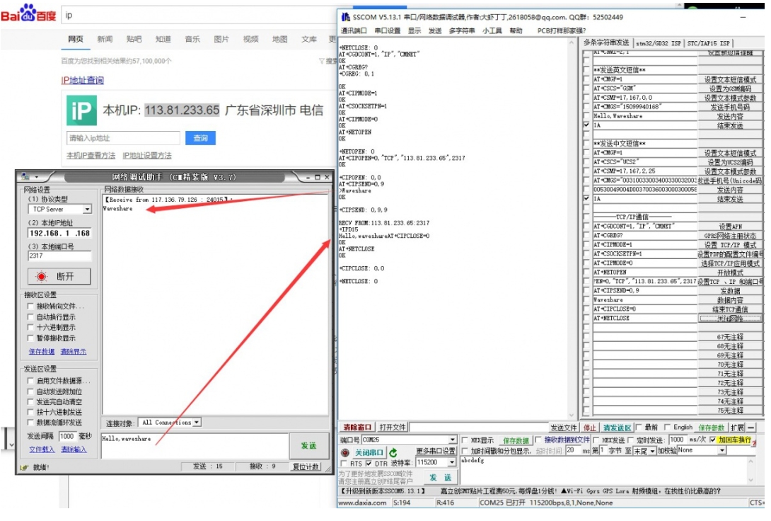
Set up a local computer virtual server
The virtual server defines the mapping relationship between the WAN service port and the LAN network server. All accesses to the WAN service port will be relocated to the LAN network server specified by the IP address. (Please refer to your router's corresponding manufacturer's manual)
Use a browser to log in to the router management interface (please refer to your router manual for the specific address)
Set the port number: 2317 (it does not conflict with the existing port number. In this example, it is set to 2317)
Set the intranet IP of the computer (the IP obtained by the computer in the local area network can be run CMD on the local machine, enter the command line prompt, enter ipconfig to check the IPv4 address, the intranet IP of the computer in this example is 192.168.1.168), as shown in the following figure :

Configure GPRS
The operation is shown in the following figure:
Call Phone
Refer to the "Hardware Configuration" chapter to connect the LTE antenna, SIM card (the phone function must be enabled), and the headset cable with microphone, and the module is turned on.
Common commands for making calls:
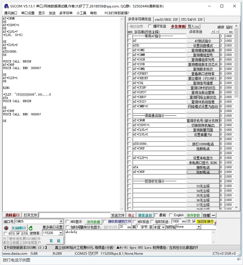
AT+CNUM
Check the phone number (not all SIM cards support this command)
+CNUM OK
AT+CSDVC
AT+CSDVC=1: switch to headphone output AT+CSDVC=3: switch to speaker output
OK
AT+CLVL=?
Query volume range
OK
AT+CLVL=2
set volume to 2
OK
ATD<phone_number>;
ATD10086; Dial Mobile customer service phone number 10086
OK
AT+CHUP
set volume to 2
OK
AT+CLIP=1
Set up caller ID
OK
ATA
Answering the Phone
OK
The detailed operation screenshots are as follows:
[Note]When using the SSCOM serial port assistant to send and receive AT commands, you must click "carriage return and line feed".
Voice output mode and volume adjustment
Answer the phone
Audio parameter debugging
A.In the initialization stage of the module startup, before making a call, add the following
B. The module is in the process of establishing a voice call
See "SIM7X00_Audio_Application_Note" document for details.
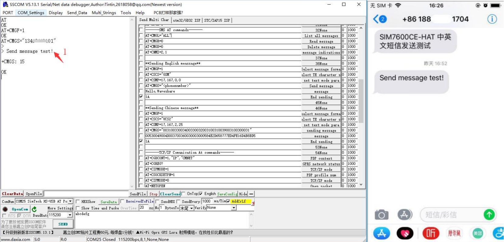
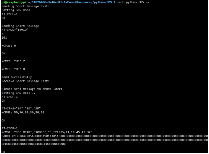
Send English SMS
1. Correctly install the SIM card and LTE antenna, connect the module's USB interface to the computer with a USB cable, and turn on the module; 2. Observe whether the indicator light is normal, the PWR indicator is always on, and the NET indicator is flashing; 3. Set the local SMS center: AT + CSCA = " + 8613800755500" + Enter, return OK.
Note: China Mobile's SMS service center number is +861380xxxx500, where xxxx is the long-distance telephone area code where you are located. The SMS center may be different from place to place. For details, you can query Baidu or call China Mobile Unicom customer service. This SMS center is Shenzhen (0755);
4. AT+CMGF=1: Set the SMS mode to TEXT; 5. AT+CMGS="phone number"<Enter>, set the recipient's phone number, and then return: ">", send the content that you need, such as "Send massage test!", You don’t need to “Enter” at the end. After editing the text message, send 1A to send information in hexadecimal format (1A is the key value of "CTRL+Z", which is used to tell the module to perform the sending operation, or 1B or "ESC" to cancel the operation). After successfully sending, the module returns + CMGS: 15 confirm that the transmission was successful. As shown below.
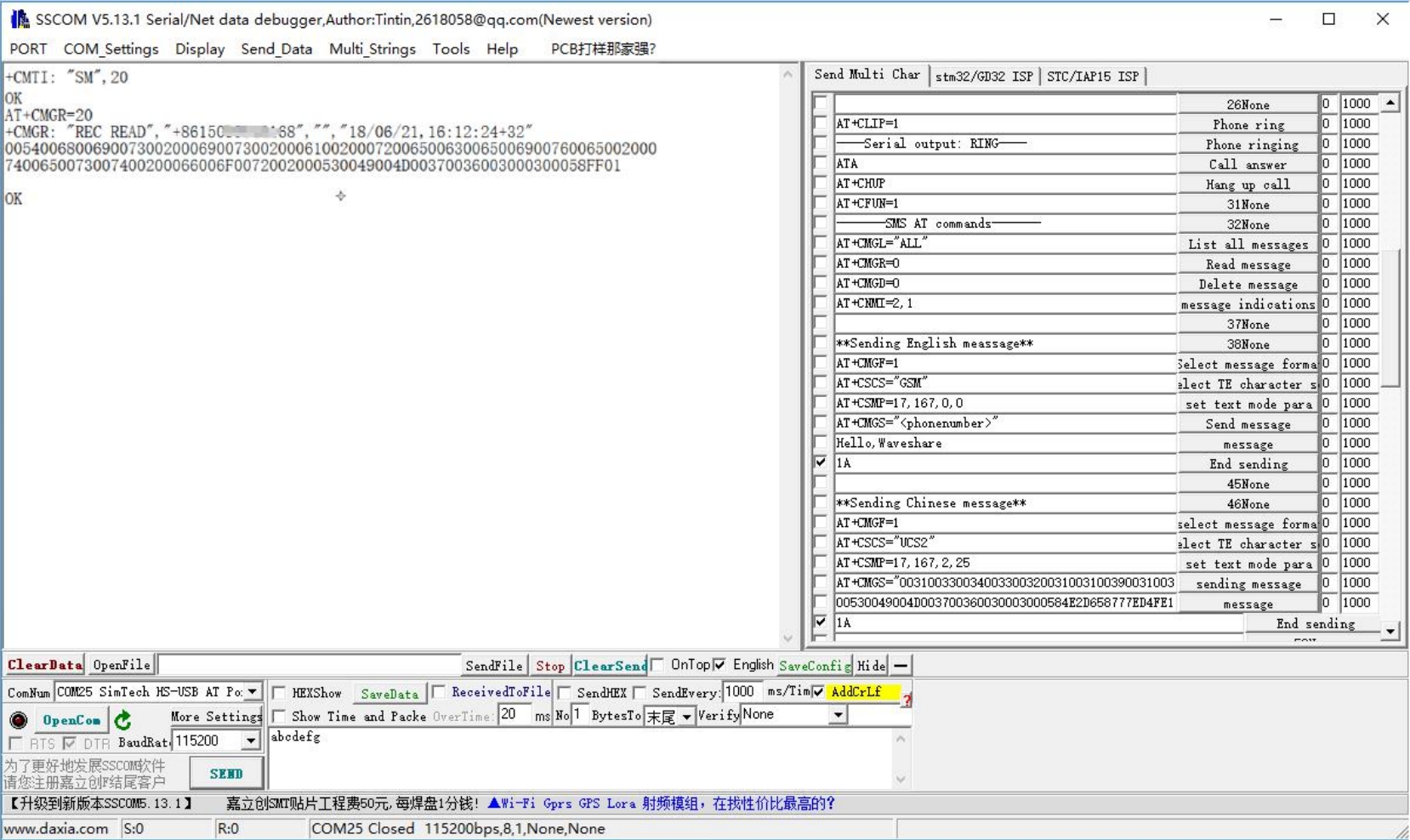
Receive English SMS
Send a message on the phone: "This is a receive test for SIM7600X!" to the test module.
When receiving the information, the serial port will break and report the information, "SM", 20, which means there are 20 pieces of information in the SM, and the message just sent is the 20th piece of information.
Read information: AT+CMGR=20 to read the 20th information (AT+CMGL="ALL" to read all information).
Delete information: AT+CMGD=20, as shown below.
Convert the displayed information to text through a code converter.
User Guides of Raspberry Pi
Raspberry Pi Internet Operation
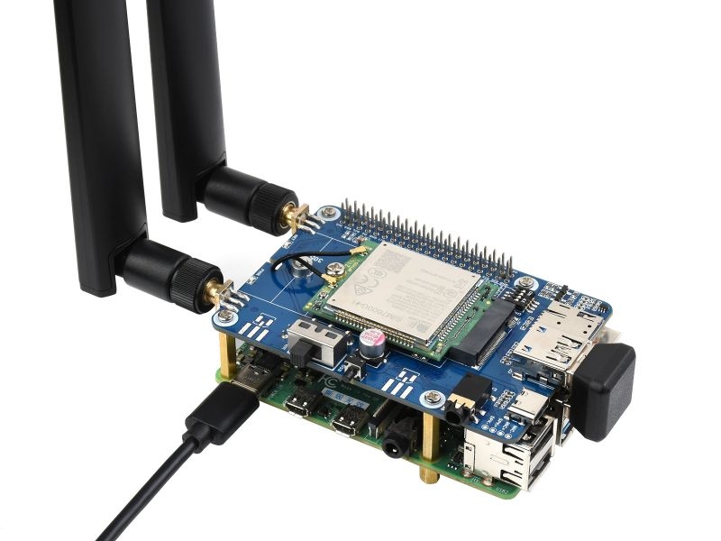
If you are using Raspberry Pi 4B, Raspberry Pi 3B+ or CM4-IO-BASE-A/B baseboard, you can use the used the customized USB adapter.if it is used for other embedded mainboards or PCs, it can be connected through the matching double-head usb3.0 data cable; as shown in the following figure: For specific operations related to Raspberry Pi dial-up Internet access, please refer to the following links:
Raspberry Pi RNDIS dial-up Internet- (the easiest way to operate)
Raspberry Pi PPP dial-up- (the operation is relatively simple)
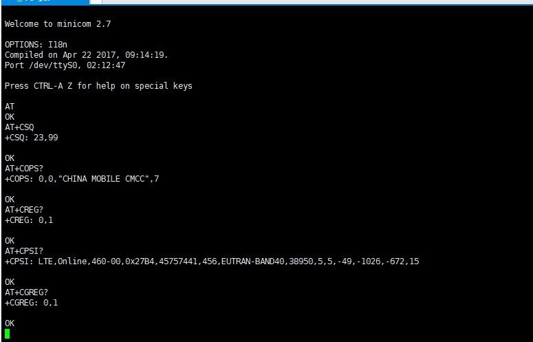
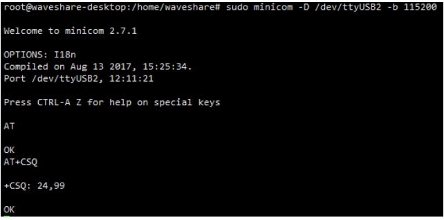
Raspberry Pi Minicom Sends AT Command to Debug
1. Connect the module to Raspberry Pi. 2. Install minicom, minicom is a serial debugging tool for the Linux platform.
3. USB and UART serial AT command debugging.
Execute minicom -D /dev/ttyUSB2. (default baud rate is 115200)
Enter the following AT command in the minicom to open the UART. (the default baud rate is 115200).
Switch on all the A silkscreen corresponding to SIM76XX, use minicom to select the corresponding serial port, Raspberry Pi 5/3B/2B/zero, the user serial port device number is ttyAMA0, and the baud rate is 115200 by default.
4. Taking the AT synchronization test as an example, send relevant commands, as shown in the following figure: * minicom can enter the setting mode by pressing Ctrl+A, then Z, and exit by selecting X. If the sending command does not display, please send the command ATE=1 + Enter -> open the echo.
Program sample
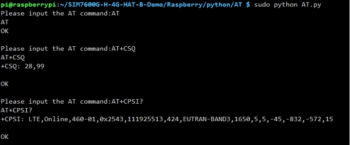
1. After inserting the module and connecting it to the Raspberry Pi; 2. Download the sample program to the /home/pi/ path;
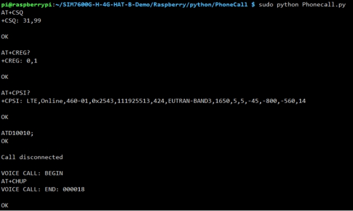
3. Go to the corresponding instance directory, compile and run the program, the relevant instructions are as follows (take the PhoneCall.py program as an example):
sudo pip3 install RPi.GPIO
AT Command
Phone Call Demo
Receive & Send SMS Note: The sample program is to send English text messages. If you have sent Chinese text messages, you need to use the following commands to change to English format:
GPS Demo
TCP Network Communication Demo
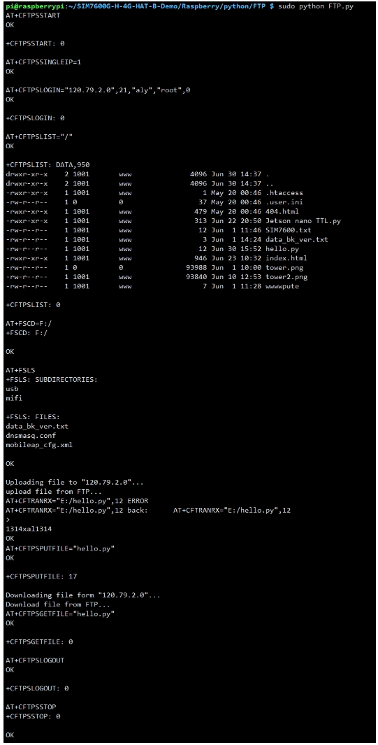
FTP Upload & Download Demo
Jetson Nano Demo
Hardware Connection
Jetson Nano has an onboard USB interface, SIM7600X 4G HAT(B) is connected to the USB interface of Jetson Nano through Micro USB.
Jetson Nano minicom Serial Port Debugging
1. Connect the SIM7600X 4G HAT(B) to the Jetson Nano and turn it on after three seconds 2. Use Template:SERIAL to log in to the Jetson Nano terminal, install minicom, and enter:
3. Run minicom for debugging, and enter in the terminal
4. Send AT command to test, exit minicom and press Ctrl+A, then X, and finally press ENTER More demos to be continued...
FAQ
When compiling the BCM2835 library, Makefile:327:recipe for target 'aclocal.m4' failed?

Execute: autoreconf -vfi, and then recompile, as shown in the following figure:

When executing the chmod 777 sim7600_4G_hat_init command, an error is reported: "chmod: cannot access 'sim7600_4G_hat_init': No such file or directory", what should I do?
![]()
Answer:Please confirm that there is a sim7600_4G_hat_init file in the current path
 The general operation is: download the sample program, after decompression, rename the c folder under the Raspberry folder to SIM7600X, then copy the entire SIM7600X folder to the Raspberry Pi /home/pi directory, and enter the command line to /home/pi /SIM7600X directory, and then execute the chmod 777 sim7600_4G_hat_init command. "
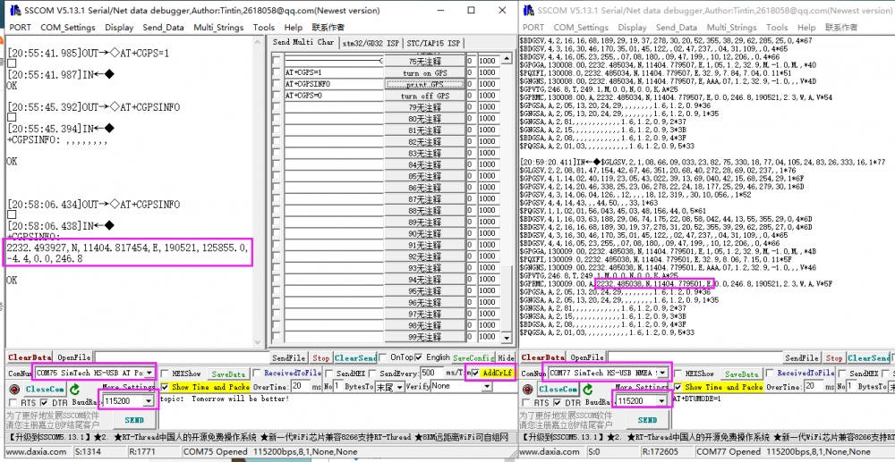
What do the positioning information obtained by SIM7600X through AT+CGPSINFO represent?
From left to right are ①Latitude, ②Longitude, ③Date, ④Time, ⑤Elevation, ⑥Speed and ⑦Angle.
.png)
SIM7600 firmware upgrade failed, and the prompt is as shown in the figure below, what should I do?
.png) 1. Pay attention to check the device manager, the new device will be prompted during the upgrade process, and there will be no device driver during the first upgrade;
2. Pay attention to the USB cable. The speed of the USB cable is higher during the upgrade process. You need to choose a better quality USB cable to avoid poor contact.
3. You need to run the upgrade tool with administrator privileges (SIM7500_SIM7600_QDL V1.41 only for Update)
4. Uninstall and reinstall the upgrade tool (SIM7500_SIM7600_QDL V1.41 only for Update)
5. For more operation details, please refer to this video: https://www.waveshare.net/wiki/SIM7600-Firmware-upgrade-Video
1. Pay attention to check the device manager, the new device will be prompted during the upgrade process, and there will be no device driver during the first upgrade;
2. Pay attention to the USB cable. The speed of the USB cable is higher during the upgrade process. You need to choose a better quality USB cable to avoid poor contact.
3. You need to run the upgrade tool with administrator privileges (SIM7500_SIM7600_QDL V1.41 only for Update)
4. Uninstall and reinstall the upgrade tool (SIM7500_SIM7600_QDL V1.41 only for Update)
5. For more operation details, please refer to this video: https://www.waveshare.net/wiki/SIM7600-Firmware-upgrade-Video
Why is my dial-up internet speed very slow here?
Generally, the default configuration of SIM7600 is to automatically select the network standard, and it is likely to choose 2G Internet access; if you need to force the use of 4G mode, you need to enter the following AT command configuration:
.png)
If 4G has been fixed, the speed is still not ideal, it may be a frequency band problem;

What should you do if you are registered to the network, dial up successfully and get an IP, but you cannot access the Internet and cannot ping through?
It may be that the APN has not been obtained. Generally, the APN can be obtained automatically. In some areas (IoT card), it needs to be obtained manually. For example, it can be set by the following instructions:

The NET light does not flash after the SIM7600X is turned on, what should I do if the network is abnormal?
In this case, it may be that you have not successfully connected to the network, you can follow the steps below to troubleshoot: 1. First check the hardware connection:
Check if the MAIN antenna is well connected;
Whether the connected SIM card can call and surf the Internet normally on mobile phones and other devices:
If the Raspberry Pi is connected, whether the module enters airplane mode;
2. After confirming that there is no problem with the hardware, the software can use these instructions:
Check whether the sim card is in good contact: AT+CPIN?
Check if the network mode setting is correct: AT+CNMP?
Check the signal quality of the current environment: AT+CSQ
Check the operator's access situation: AT+COPS?
Check the connection status: AT+CPSI?
Check whether it is successfully registered to the network: AT+CGREG?

Type of SIM card?
Support SIM standard (Standard) card, as shown in the figure below, if it is Micro or Nano card, you need to add a card sleeve.

Last updated
Was this helpful?