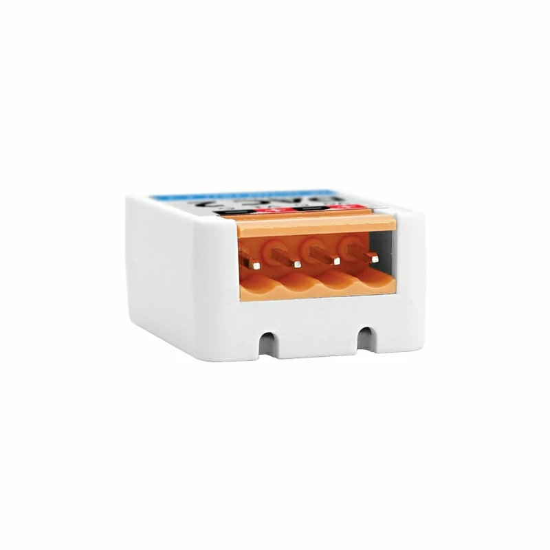
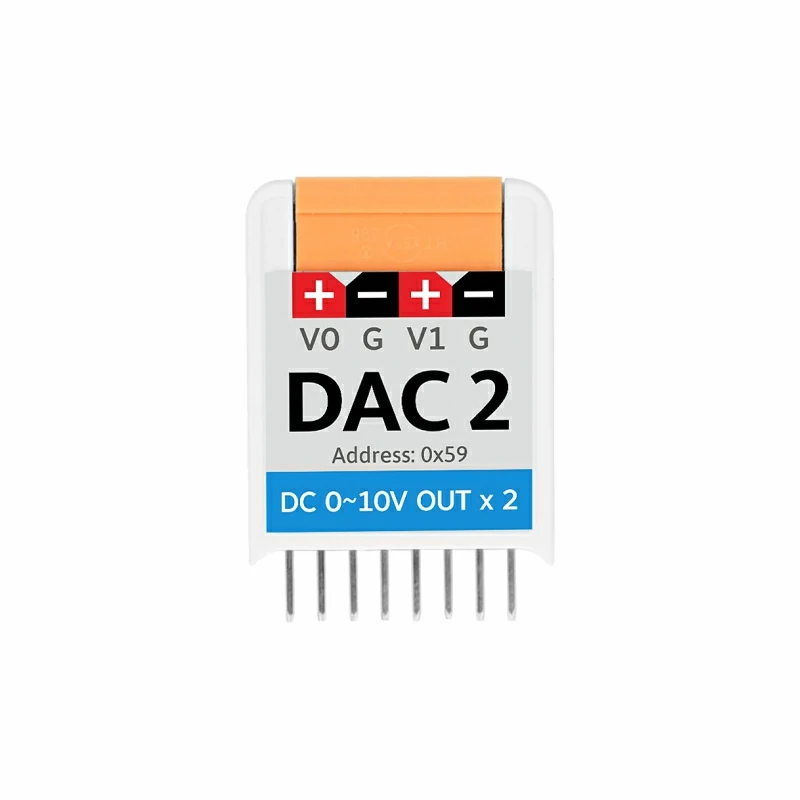
M5Stack M5StickC DAC 2 Hat
Product Link
Description
DAC2 Hat is an I2C digital-to-analog signal conversion unit designed to be compatible with the StickC series controllers. It offers high precision and accuracy in its performance by using the GP8413 solution. This chip can linearly convert a 15-bit digital value into two independent analogue voltages of 0-5V or 0-10V. The output voltage error is only 0.2%, with a linearity of up to 0.01%.
For scalability, the circuit design supports a 3-bit hardware address, allowing up to 8 devices to be connected and operated simultaneously. The DAC2 Hat also incorporates safety features such as output short-circuit protection. In the event of a short circuit between the output pins and ground, it automatically enters a protective mode and shuts down the output to prevent damage.
DAC2 Hat is suitable for a variety of applications including general signal conversion, motor speed control, LED dimming, inverters, power supplies and industrial analogue signal isolation. It provides a reliable solution for converting digital signals to analogue, offering high accuracy, expandability and safety.and safety performance.
Features
Adapted StickC/StickC PLUS/StickC PLUS2
I2C communication (default address 0x59)
Supports multiple parallel connections
Short-circuit protection
High precision, small error
Includes
1x DAC2 Hat
1x VH3.96-4P
1x Sticker
Applications
Universal signal conversion
Motor speed regulation, LED dimming
Inverter, power supply
Industrial analog signal isolation
Specification
DAC Chip
GP8413
Resolution Ratio
15Bit
I2C Serial Communication
0x59 (default)
Maximum Output Voltage
10V
Output Voltage Error
<0.2%
Output Voltage Linearity error
0.01%
Operating Temperature
0-40°C
Product Size
35* 24* 13.7mm
Package Size
136* 92* 13.7mm
Product Weight
6.7g
Package Weight
15g


Related Link
Schematic

Address Select

0
0
0
0x58
0
0
1
0x59(Default)
0
1
0
0x5A
0
1
1
0x5B
1
0
0
0x5C
1
0
1
0x5D
1
1
0
0x5E
1
1
1
0x5F
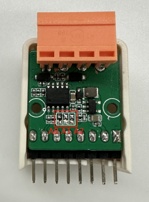
Address SelectBy setting the A0, A1, A2 pins to high (1) or low (0), you get eight different I2C addresses from 0x58 to 0x5F. *If the resistance is connected, it is regarded as high(1), and if the resistance is not connected, it is low(0) .
PinMap
DAC2 Hat
G0
G26
5V
GND
Module Size

Examples
Arduino
UIFlow

UIFlow1.0 Blockly dac2 Instructions for useUIFlow1.0 Blockly dac2 Instructions for useHow to use Blockly dac2 on the UIFlow 1.0 graphical programming platform and related API instructions
FAQ
Difference between Hat-DAC2 and Hat-DAC?
DAC2 Hat
I2C
GP8413
/
15Bit
0-10V
Adjustable A0/A1/A2(8 I2C addresses) (default 0x59)
Two-Channel
DAC Hat
I2C
MCP4725
Support
12Bit
VDD(0-3.3V)
The default is 0x60, unchangeable
Singal-Channel
Last updated
Was this helpful?
