Seeed Studio reComputer J4011B Edge AI Computer NVIDIA® Orin™ NX 8GB
Product Link
Description
The reComputer J401B series is an iteration on reComputer Classic series. The reComputer J4011B with NVIDIA Jetson Orin NX 8GB modules is a powerful and compact edge AI device with rich interfaces: 2x USB 3.2, HDMI, Ethernet, M.2 Key E for Wi-Fi module, M.2 Key M for SSD, mini-PCIe for LTE module, CAN, 40-pin and more.
Features
Build the Most Powerful Embedded AI Platform: Compatible with the Jetson Orin NX module, offering up to 100 TOPS.
Design for Both Development and Production: Equip with rich set of I/Os: 2x USB3.2, HDMI, Ethernet, M.2 Key M, M.2 Key E, mini-PCIe, 40-pin GPIO, etc. Support multiple wired and wireless commnucation including Wi-Fi and LTE
Immediately Go-to-Market: Pre-installed JetPack5.1.3, Linux OS BSP ready
Certification includes ROHS, CE, FCC, KC, UKCA, REACH
Long Life Time Supply:Production Lifetime: until at least 2032
Specifications
Specifications
reComputer J3010B
reComputer J3011B
reComputer J4011B
reComputer J4012B
Module
Jetson Orin Nano 4GB
Jetson Orin Nano 8GB
Jetson Orin NX 8GB
Jetson Orin NX 16GB
AI Performance
20 TOPS
40 TOPS
70 TOPS
100 TOPS
GPU
512-core NVIDIA Ampere architecture GPU with 16 Tensor Cores
1024-core NVIDIA Ampere architecture GPU with 32 Tensor Cores
1024-core NVIDIA Ampere architecture GPU with 32 Tensor Cores
GPU Max Frequency
625 MHz
765 MHz
918 MHz
CPU
6-core Arm® Cortex®-A78AE v8.2 64-bit CPU 1.5MB L2 + 4MB L3
6-core Arm® Cortex®-A78AE v8.2 64-bit CPU 1.5MB L2 + 4MB L3
8-core Arm® Cortex®-A78AE v8.2 64-bit CPU 2MB L2 + 4MB L3
CPU Max Frequency
1.5 GHz
2 GHz
Memory
4GB 64-bit LPDDR5 34 GB/s
8GB 128-bit LPDDR5 68 GB/s
8GB 128-bit LPDDR5 102.4GB/s
16GB 128-bit LPDDR5 102.4GB/s
DL Accelerator
/
1x NVDLA v2
2x NVDLA v2
DLA Max Frequency
/
614 MHz
Vision Accelerator
/
1x PVA v2
Storage
128GB NVMe SSD
Video Encoder
1080p30 supported by 1-2 CPU cores
1x 4K60 (H.265) | 3x 4K30 (H.265) 6x 1080p60 (H.265) | 12x 1080p30 (H.265)
Video Decoder
1x 4K60 (H.265) 2x 4K30 (H.265) 5x 1080p60 (H.265) 11x 1080p30 (H.265)
1x 8K30 (H.265) | 2x 4K60 (H.265) | 4x 4K30 (H.265) 9x 1080p60 (H.265) | 18x 1080p30 (H.265)
Display
1* HDMI 2.1
CSI Camera
2* CSI (2-lane 15pin)
Networking
1* Gigabit Ethernet (10/100/1000M)
USB
2* USB 3.2 Type-A (10Gbps); 1* USB2.0 Type-C (Device Mode)
M.2 Key M
1* M.2 Key M
M.2 Key E
1* M.2 Key E
Mini PCIe
1* mini-PCIe for LTE module
Fan
1* 4 pin Fan Connector(5V PWM)
CAN
1* CAN
Multifunctional Port
1* 40-Pin Expansion header,1* 12-Pin Control and UART header
RTC
RTC 2-pin, RTC socket (supports CR1220 but not included)
Power
DC 9-19V via 5525 DC jack
Power Supply
Power adapter not included
Temperature
-10℃~60℃
Mechanical
130mm x120mm x 58.5mm
Danger:
reComputer J401B series comes with JetPack 5.1.3 pre-installed on the included NVMe SSD, so that you do not need to flash it. However, if you want to flash it again with JetPack, you can follow this guide.
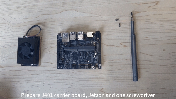
J401B Interfaces Usage

Mini-PCIe
reComputer J401B comes with a mini PCIe connector that supports 4G.
Supported 4G Module
LTE Cat 4 EC25-AFXGA
LTE Cat 4 EC25-EUX
LTE Cat 4 EC25-AUXGR
LTE Cat 4 EC25-EFA
LTE Cat 4 EC25-EMGA
LTE Cat 4 EC25-JFA
Connection Overview
Step1. Install the 4G Module
Step2. Attach the Antennas
Step3. Insert the SIM Card
Usage
Setp1. Open Mobile Broadband and configure the network connection according to the specifications of the 4G SIM card.
Settings-->Network-->Mobile BroadbandSetp2. Open a browser to test if the 4G network is functioning properly.
Connection Overview
note:
If the connection is correct, when you connect your power adapter, you will see the power indicator light up.
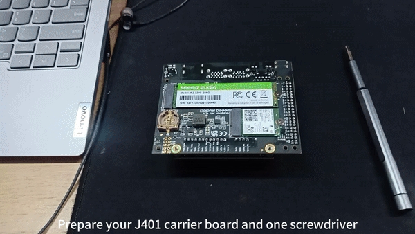
M.2 Key M
M.2 Key M is a specification for the physical and electrical layout of an M.2 connector that supports high-speed data transfer using the PCIe (Peripheral Component Interconnect Express) interface. M.2 Key M connectors are commonly used for connecting solid-state drives (SSDs) and other high-performance expansion cards to a motherboard or other host device. The "Key M" designation refers to the specific pin configuration and keying of the M.2 connector, which determines the type of devices that can be connected to it.
Supported SSD are as follows:
128GB NVMe M.2 PCle Gen3x4 2280 Internal SSD
256GB NVMe M.2 PCle Gen3x4 2280 Internal SSD
512GB NVMe M.2 PCle Gen3x4 2280 Internal SSD
1TB NVMe M.2 PCle Gen3x4 2280 Internal SSD
2TB NVMe M.2 PCle Gen3x4 2280 Internal SSD
Connection Overview
If you want to remove the included SSD and install a new one, you can follow the steps below.
Usage
We will explain how to do a simple benchmark on the connected SSD.
Step 1: Check the write speed by executing the below command.
Step 2: Check the read speed by executing the below commands. Make sure to execute this after executing the above command for write speed.
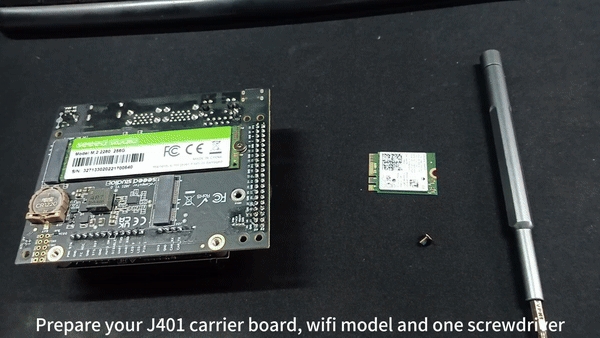
M.2 Key E
M.2 Key E is a specification for the physical and electrical layout of an M.2 connector that supports wireless communication modules, such as Wi-Fi and Bluetooth cards. The "Key E" designation refers to the specific pin configuration and keying of the M.2 connector, which is optimized for wireless networking devices. M.2 Key E connectors are commonly found on motherboards and other devices that require wireless connectivity options.Here we recommand Intel wifi/bluetooth module.
Connection Overview
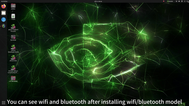
Usage
After installing wifi/bluetooth module, you can see the wifi/bluetooth icon in the top right corner.
Wi-Fi test
Bluetooth test

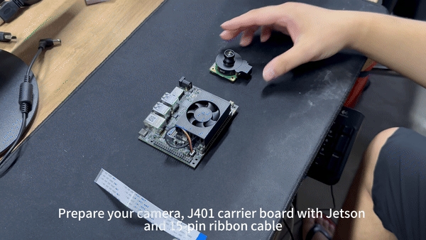
CSI Cameras
CSI stands for Camera Serial Interface. It is a specification that describes a serial communication interface for transferring video data from image sensors to a host processor. CSI is commonly used in mobile devices, cameras, and embedded systems to enable high-speed and efficient transfer of image and video data for processing and analysis.
Supported cameras are as follows:
IMX219 cameras
Raspberry Pi Camera V2
IMX219-77 8MP Camera with 77° FOV
IMX219 M12/CS mount CMOS Camera Module
IMX219-83 8MP 3D Stereo Camera Module
IMX219-77IR 8MP IR Night Vision Camera with 77° FOV
IMX219-160IR 8MP Camera with 160° FOV
IMX477 cameras
Raspberry Pi High Quality Camera
Raspberry Pi HQ Camera - M12 mount
High Quality Camera for Raspberry Pi
Connection Overview
Here the 2 CSI camera connectors are marked as CAM0 and CAM1. You can either connect one camera to any connector out of the 2 or connect 2 cameras to both the connectors at the same time.
Usage
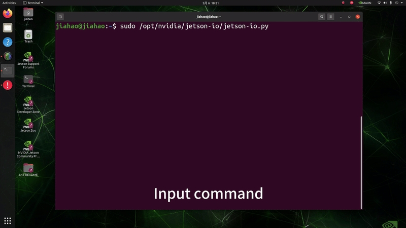
Open your terminal(Ctrl+Alt+T) and input command like below:
For CAM0 port
For CAM1 port
note:
If you want to change further settings of the camera, you can type "nvgstcapture-1.0 --help" to access all the configurable options available.
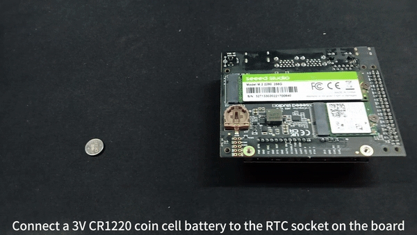
RTC
RTC stands for Real-Time Clock. It is a clock that keeps track of the current time and date independently of the main system clock. RTCs are commonly used in computers, embedded systems, and other electronic devices to maintain accurate timekeeping even when the device is powered off. They are often powered by a small battery to ensure continuous operation and retain time and date information during power cycles.
Connection Overview
Connect a 3V CR1220 coin cell battery to the RTC socket on the board as shown below. Make sure the positive (+) end of the battery is facing upwards.
Usage
Step 1: Connect an RTC battery as mentioned above.
Step 2: Turn on reComputer Industrial.
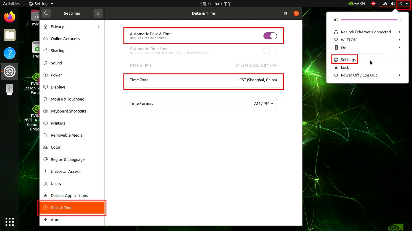
Step 3: On the Ubuntu Desktop, click the drop-down menu at the top right corner, navigate to
Settings > Date & Time, connect to a network via an Ethernet cable and select Automatic Date & Time to obtain the date/ time automatically.
note:
If you have not connected to internet via Ethernet, you can manually set the date/time here.
Step 4: Open a terminal window, and execute the below command to check the hardware clock time.
You will see the output something like below which is not the correct date/time.

Step 5: Change the hardware clock time to the current system clock time by entering the below command.
Step 6: Remove any Ethernet cables connected to make sure it will not grab the time from the internet and reboot the board.
Step 7: Check hardware clock time to verify that the date/ time stays the same eventhough the device was powered off.
Step 8: Create a new shell script using any text editor of your preference. Here we use vi text editor.
Step 9: Enter insert mode by pressing i, copy and paste the following content inside the file.
Step 10: Make the script executable.
Step 11: Create a systemd file.
Step 12: Add the following inside the file.
Step 13: Reload systemctl daemon.
Step 14: Enable the newly created service to start on boot and start the service.
Step 15: Verify the script is up and running as a systemd service.
Step 16: Reboot the board and you will the system clock is now in sync with the hardware clock.
Fan control
nvfancontrol is a userspace fan speed control daemon. This manages the fan speed based on the temperature-to-fan-speed mapping table in the nvfancontrol configuration file.
There are some basic elements in the nvfancontrol service, including Tmargin, kickstart PWM, fan profile, fan control, and fan governor. All of these can be programmed via the configuration file based on the user’s preferences. This chapter will explain each of them in the following sections.
note:
If you want to change nvfancontrol.conf make sure you have read it
Usage
Step 1: Stop the nvfancontrol systemd service.
Step 2: Change nvfancontrol.conf.
note:
After you change nvfancontrol.conf, print Ese and :q to quit
Step 3: Remove the status file.
Step 4: Restart nvfancontrol systemd service.
GPIO
The detail of 40-pin header is shown below:
1
-
-
-
Main 3.3V Supply
-
2
-
-
-
Main 5.0V Supply
-
3
I2C1_SDA
191
DP_AUX_CH3_N
I2C #1 Data
-
4
-
-
-
Main 5.0V Supply
-
5
I2C1_SCL
189
DP_AUX_CH3_P
I2C #1 Clock
-
6
-
-
-
Ground
-
7
GPIO09
211
AUD_MCLK
GPIO
Audio Master Clock
8
UART1_TXD
203
UART1_TX
UART #1 Transmit
GPIO
9
-
-
-
Ground
-
10
UART1_RXD
205
UART1_RX
UART #1 Receive
GPIO
11
UART1_RTS*
207
UART1_RTS
GPIO
UART #2 Request to Send
12
I2S0_SCLK
199
DAP5_SCLK
GPIO
Audio I2S #0 Clock
13
SPI1_SCK
106
SPI3_SCK
GPIO
SPI #1 Shift Clock
14
-
-
-
Ground
-
15
GPIO12
218
TOUCH_CLK
GPIO
-
16
SPI1_CSI1*
112
SPI3_CS1
GPIO
SPI #1 Chip Select #1
17
-
-
-
GPIO
-
18
SPI1_CSI0*
110
SPI3_CS0
GPIO
SPI #0 Chip Select #0
19
SPI0_MOSI
89
SPI1_MOSI
GPIO
SPI #0 Master Out/Slave In
20
-
-
-
Ground
-
21
SPI0_MISO
93
SPI1_MISO
GPIO
SPI #0 Master In/Slave Out
22
SPI1_MISO
108
SPI3_MISO
GPIO
SPI #1 Master In/Slave Out
23
SPI0_SCK
91
SPI1_SCK
GPIO
SPI #0 Shift Clock
24
SPI0_CS0*
95
SPI1_CS0
GPIO
SPI #0 Chip Select #0
25
-
-
-
Ground
-
26
SPI0_CS1*
97
SPI1_CS1
GPIO
SPI #0 Chip Select #1
27
I2C0_SDA
187
GEN2_I2C_SDA
I2C #0 Data
GPIO
28
I2C0_SCL
185
GEN2_I2C_SCL
I2C #0 Clock
GPIO
29
GPIO01
118
SOC_GPIO41
GPIO
General Purpose Clock #0
30
-
-
-
Ground
-
31
GPIO11
216
SOC_GPIO42
GPIO
General Purpose Clock #1
32
GPIO07
206
SOC_GPIO44
GPIO
PWM
33
GPIO13
228
SOC_GPIO54
GPIO
PWM
34
-
-
-
Ground
-
35
I2S0_FS
197
DAP5_FS
GPIO
Audio I2S #0 Field Select
36
UART1_CTS*
209
UART1_CTS
GPIO
UART #1 Clear to Send
37
SPI1_MOSI
104
SPI3_MOSI
GPIO
SPI #1 Master Out/Slave In
38
I2S0_DIN
195
DAP5_DIN
GPIO
Audio I2S #0 Data in
39
-
-
-
Ground
-
40
I2S0_DOUT
193
DAP5_DOUT
GPIO
Audio I2S #0 Data Out
UART
UART stands for Universal Asynchronous Receiver/Transmitter. It is a communication protocol used for serial communication between two devices. UART communication involves two pins: one for transmitting data (TX) and one for receiving data (RX). It is asynchronous, meaning that data is transmitted without a shared clock signal between the devices. UART is commonly used in various applications such as microcontrollers, sensors, and communication between different electronic devices.
Connection Overview
The UART interface is using the pin below, or you can use another UART interface on J401:
6
-
-
-
Ground
-
8
UART1_TXD
203
UART1_TX
UART #1 Transmit
GPIO
10
UART1_RXD
205
UART1_RX
UART #1 Receive
GPIO
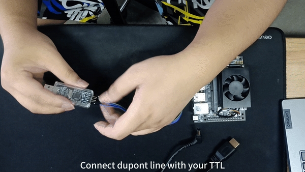
Connect the J401 with TTL with UART as below:
6
Ground
GND
Ground
8
UART1_TXD
U_RX
UART_RX
10
UART1_RXD
U_TX
UART_TX
Usage
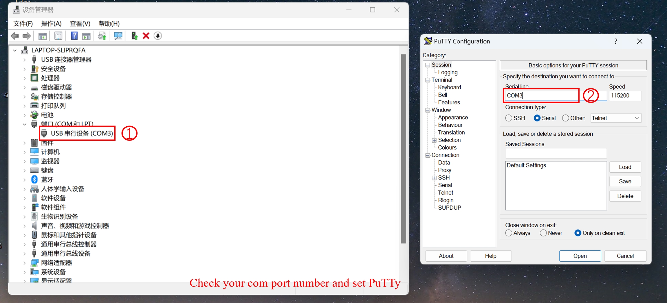
Step 1: Install PuTTy on your windows laptop, and set PuTTy as below:
Step 2: Install PuTTy on Jetson, open your terminal(ALT+Ctrl+T) and type the following command.
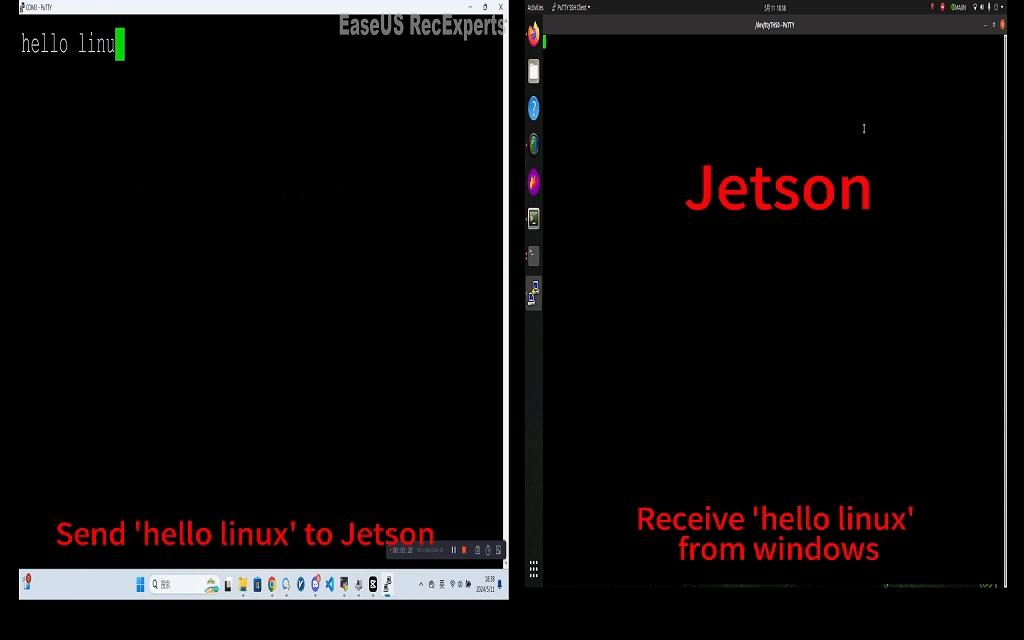
Step 3: Use PuTTy on Windows send 'hello linux' to Jetson, and use PuTTy on Jetson send 'hello windows' to windwos.
note:
Make sure your baudrate have be set 115200.
The result is as below:
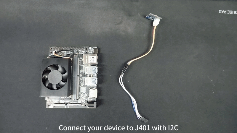
I2C
I2C stands for Inter-Integrated Circuit. It is a widely used serial communication protocol that enables communication between multiple integrated circuits in a system. I2C uses two bidirectional lines: one for data (SDA) and one for clock (SCL). Devices connected on an I2C bus can act as either a master or a slave, allowing for multiple devices to communicate with each other. I2C is popular for its simplicity, flexibility, and ability to connect a variety of devices such as sensors, memory chips, and other peripherals in embedded systems and electronic devices.
Connection Overview
The I2C interface is using pin as below, or you can use other I2C interface on J401:
2
-
-
-
Main 5.0V Supply
-
3
I2C1_SDA
191
DP_AUX_CH3_N
I2C #1 Data
-
5
I2C1_SCL
189
DP_AUX_CH3_P
I2C #1 Clock
-
6
-
-
-
Ground
-
Connect the J401 to Grove-3-Axis Digital Accelerometer with I2C as below:
2
5V supply
Vcc
-
3
I2C1_SDA
SDA
I2C_SDA
5
I2C1_SCL
SCL
I2C_SCL
6
Ground
GND
Ground
Test
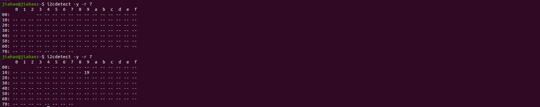
Open your terminal(ALT+Ctrl+T) and type the following command:
note
Your channel may be different from mine in the commmand: i2cdetect -y -r x.
You will see the result as below, before connecting to the I2C, no I2C device was detected on channel 7, but afterwards an I2C device with the address 0x19 was detected.:
Last updated
Was this helpful?