Seeed Studio XIAO ESP32S3 Sense 2.4GHz Wi-Fi BLE 5.0 OV2640 Camera
Product Link
Description
Seeed Studio XIAO Series are diminutive development boards, sharing a similar hardware structure, where the size is literally thumb-sized. The code name "XIAO" here represents its half feature "Tiny", and the other half will be "Puissant". Seeed Studio XIAO ESP32S3 Sense integrates camera sensor, digital microphone and SD card supporting. Combining embedded ML computing power and photography capability, this development board can be your great tool to get started with intelligent voice and vision AI.
Features
Powerful MCU Board: Incorporate the ESP32S3 32-bit, dual-core, Xtensa processor chip operating up to 240 MHz, mounted multiple development ports, Arduino / MicroPython supported
Advanced Functionality (for Sense): Detachable OV2640 camera sensor for 1600*1200 resolution, compatible with OV5640 camera sensor, intergating additional digital microphone
Elaborate Power Design: Lithium battery charge management capability, offer 4 power consumption model which allows for deep sleep mode with power consumption as low as 14μA
Great Memory for more Possibilities: Offer 8MB PSRAM and 8MB FLASH (16MB in Plus version), supporting SD card slot for external 32GB FAT memory (only for XIAO ESP32S3)
Outstanding RF performance: Support 2.4GHz Wi-Fi and BLE dual wireless communication, support 100m+ remote communication when connected with U.FL antenna
Thumb-sized Compact Design: 21 x 17.8mm, adopting the classic form factor of XIAO, suitable for space limited projects like wearable devices
Specifications
Processor
ESP32-S3R8 Xtensa LX7 dual-core, 32-bit processor that operates at up to 240 MHz
Wireless
Complete 2.4GHz Wi-Fi subsystem BLE: Bluetooth 5.0, Bluetooth mesh
Built-in Sensors
-
OV2640 camera sensor for 1600*1200 Digital microphone
-
Memory
On-chip 8M PSRAM & 8MB Flash
On-chip 8M PSRAM & 8MB Flash Onboard SD Card Slot, supporting 32GB FAT
On-chip 8M PSRAM & 16MB Flash
Interface
1x UART, 1x IIC, 1x IIS, 1x SPI, 11x GPIOs (PWM), 9x ADC, 1x User LED, 1x Charge LED 1x Reset button, 1x Boot button
1x UART, 1x IIC, 1x IIS, 1x SPI, 11x GPIOs (PWM), 9x ADC, 1x User LED, 1x Charge LED, 1x B2B Connector (with 2 additional GPIOs), 1x Reset button, 1x Boot button
2x UART, 1x IIC, 1x IIS, 2x SPI, 18x GPIOs (PWM), 9x ADC, 1x User LED, 1x Charge LED, 1x B2B Connector, 1x Reset button, 1x Boot button
Dimensions
21 x 17.8mm
21 x 17.8 x 15mm (with expansion board)
21 x 17.8mm
Power
Input voltage (Type-C): 5V Input voltage (BAT): 4.2V
Circuit operating Voltage (ready to operate): - Type-C: 5V@19mA - BAT: 3.8V@22mA
Circuit operating Voltage (ready to operate): - Type-C: 5V@38.3mA - BAT: 3.8V@43.2mA (with expansion board)
Circuit operating Voltage (ready to operate): - Type-C: 5V@28mA - BAT: 3.8V@35mA
-
Webcam Web application: - Type-C: - - Average power consumption: 5V/138mA - - Photo moment: 5V/341mA - Battery: - - Average power consumption: 3.8V/154mA - - Photo moment: 3.8V/304mA
-
-
Microphone recording & SD card writing: - Type-C: - - Average power consumption: 5V/46.5mA - - Peak power consumption: 5V/89.6mA - Battery: - - Average power consumption: 3.8V/54.4mA - - Peak power consumption: 3.8V/108mA
-
Charging battery current: 100mA
Low Power Consumption Model
Modem-sleep Model: 3.8V/25 mA Light-sleep Model: 3.8V/2 mA Deep Sleep Model: 3.8V/14 μA
Without any peripherals: - Modem-sleep Model: 3.8V/25.5 mA - Light-sleep Model: 3.8V/2.4 mA - Deep Sleep Model: 3.8V/63.768 μA Connect the camera: - Modem-sleep Model: 3.8V/44.57 mA - Light-sleep Model: 3.8V/5.47 mA - Deep Sleep Model: 3.8V/3.00 mA Connecting an SD Card: - Modem-sleep Model: 3.8V/32.8 mA - Light-sleep Model: 3.8V/3.48 mA - Deep Sleep Model: 3.8V/1.08 mA Simultaneously connect the camera and the SD card: - Modem-sleep Model: 3.8V/55.72 mA - Light-sleep Model: 3.8V/6.56 mA - Deep Sleep Model: 3.8V/3.98 mA
Modem-sleep Model: 3.8V/26.5 mA Light-sleep Model: 3.8V/2.2 mA Deep Sleep Model: 3.8V/69 μA
Wi-Fi Enabled Power Consumption
Active Model: ~ 100 mA
Active Model: ~ 110 mA (with expansion board)
Active Model: ~ 85 mA
BLE Enabled Power Consumption
Active Model: ~ 85 mA
Active Model: ~ 102 mA (with expansion board)
Active Model: ~ 77 mA
Working Temperature
-40°C ~ 65°C
Hardware
Before everything starts, it is quite essential to have some basic parameters of the product. The following table provides information about the characteristics of XIAO ESP32S3.
XIAO ESP32S3/XIAO ESP32S3 Sense
XIAO ESP32S3 Plus
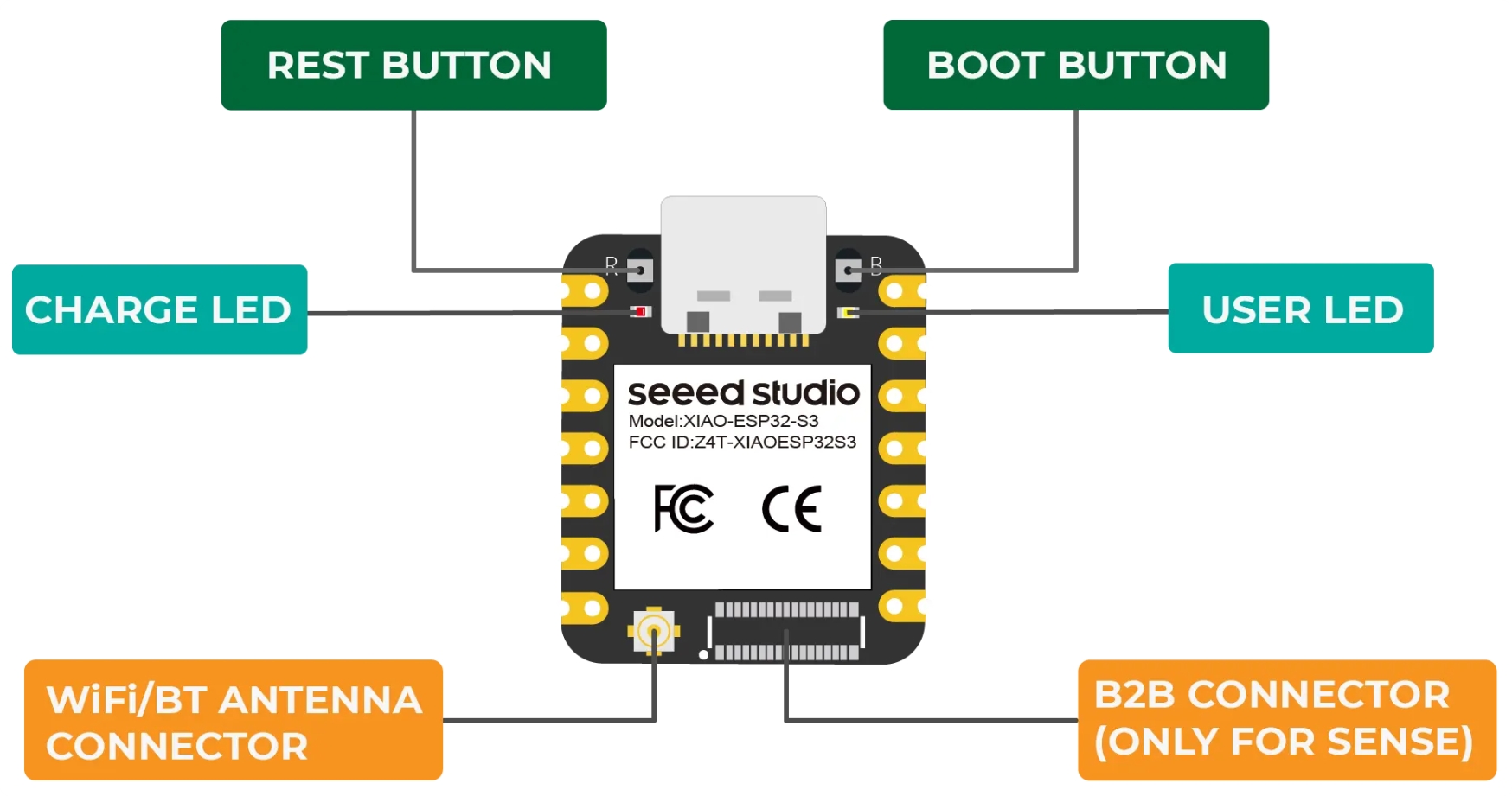
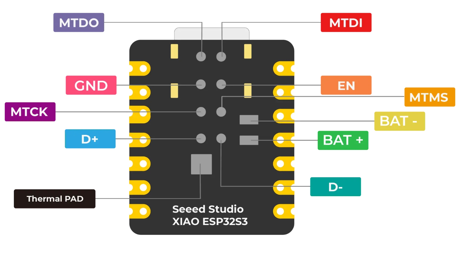
XIAO ESP32S3/XIAO ESP32S3 Sense back indication diagram
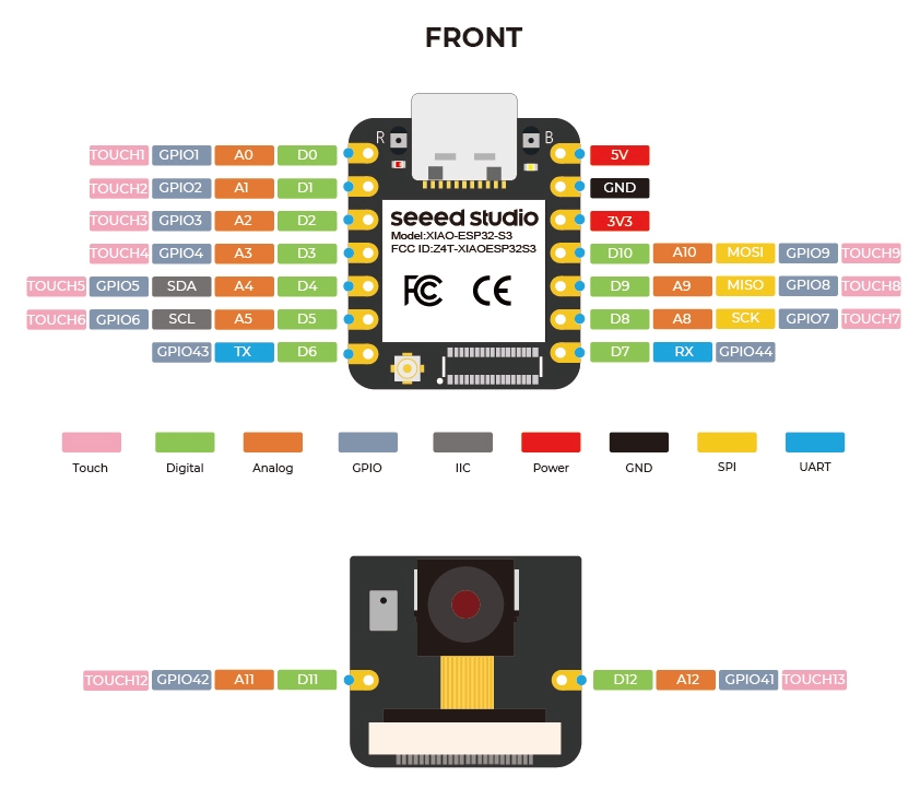
XIAO ESP32S3/XIAO ESP32S3 Sense Pin List
Power Pins
5V - This is 5v out from the USB port. You can also use this as a voltage input but you must have some sort of diode (schottky, signal, power) between your external power source and this pin with anode to battery, cathode to 5V pin.
3V3 - This is the regulated output from the onboard regulator. You can draw 700mA
GND - Power/data/signal ground
Strapping Pins
At each startup or reset, a chip requires some initial configuration parameters, such as in which boot mode to load the chip, voltage of flash memory, etc. These parameters are passed over via the strapping pins. After reset, the strapping pins operate as regular IO pins.
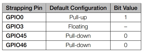
The parameters controlled by the given strapping pins at chip reset are as follows:
Chip boot mode – GPIO0 and GPIO46
VDD_SPI voltage – GPIO45
ROM messages printing – GPIO46
JTAG signal source – GPIO3
GPIO0, GPIO45, and GPIO46 are connected to the chip’s internal weak pull-up/pull-down resistors at chip reset. These resistors determine the default bit values of the strapping pins. Also, these resistors determine the bit values if the strapping pins are connected to an external high-impedance circuit.
To change the bit values, the strapping pins should be connected to external pull-down/pull-up resistances. If the ESP32-S3 is used as a device by a host MCU, the strapping pin voltage levels can also be controlled by the host MCU.
All strapping pins have latches. At system reset, the latches sample the bit values of their respective strapping pins and store them until the chip is powered down or shut down. The states of latches cannot be changed in any other way. It makes the strapping pin values available during the entire chip operation, and the pins are freed up to be used as regular IO pins after reset.
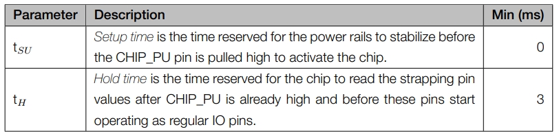
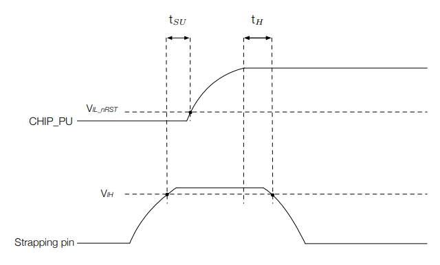
Regarding the timing requirements for the strapping pins, there are such parameters as setup time and hold time.
Battery Usage
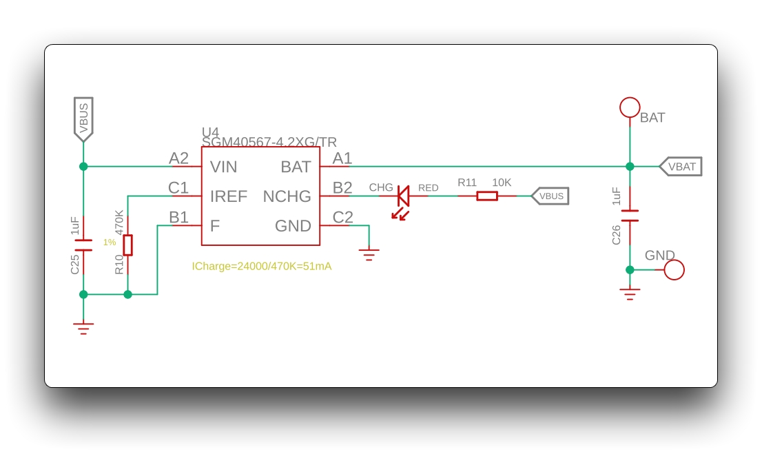
The XIAO ESP32S3 series has a built-in power management chip that allows the XIAO ESP32S3 to be powered independently by using a battery or to charge the battery through the XIAO ESP32S3's USB port.
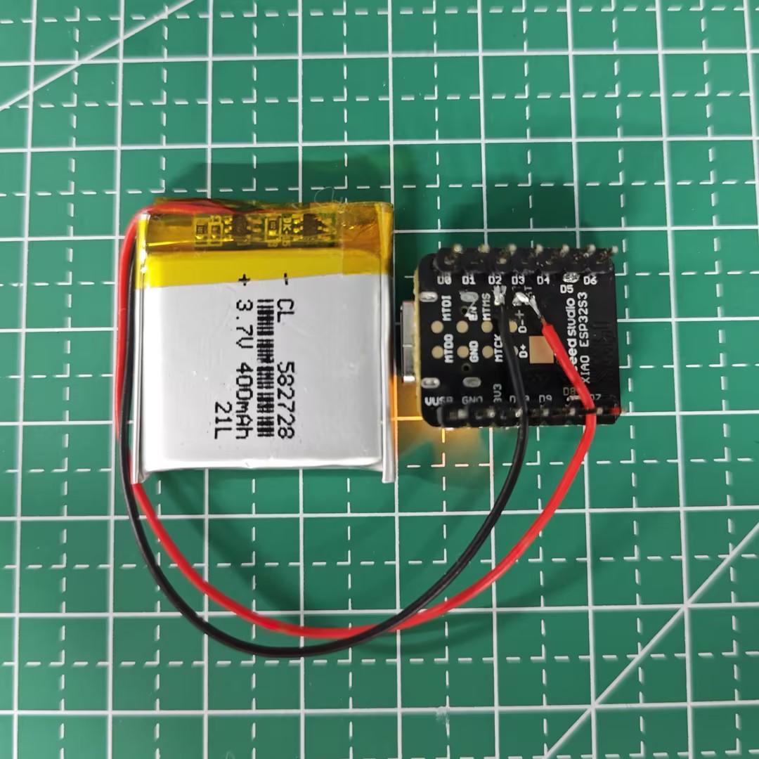
If you want to connect the battery for XIAO, we recommend you to purchase qualified rechargeable 3.7V lithium battery. When soldering the battery, please be careful to distinguish between the positive and negative terminals. The negative terminal of the power supply should be the side closest to the USB port, and the positive terminal of the power supply is the side away from the USB port.
note:
Since all GPIO pins of the XIAO ESP32S3 are assigned their own functions, we do not have a GPIO configured for the battery pin. this means that we cannot get the battery voltage at the software level by reading the analog value of one of the GPIOs. If necessary, you can consider connecting the positive and negative terminals of the battery to two of the pins to measure the battery voltage.
caution:
When you use battery power, there will be no voltage on the 5V pin.
At the same time, we designed a red indicator light for battery charging, through the indicator light display to inform the user of the current state of the battery in the charge.
When XIAO ESP32S3 is not connected to the battery, the red light comes on when the Type-C cable is connected and goes off after 30 seconds.
The red light flashes when the battery is connected and the Type-C cable is connected for charging.
When connecting Type-C to charge the battery fully, the red light turns off.
Last updated
Was this helpful?