0.91 inch OLED I2C Display 128 x 32 pixels
Product Link
Introduction
This is a general OLED display Module, 0.91inch diagonal, 128x32 pixels, with embedded controller, communicating via I2C interface.

Features
0.91inch small form factor
128x32 high resolution
I2C interface, requires only two signal pins
Comes with development resources and manual (examples for Raspberry Pi/Jetson Nano/Arduino/STM32)
Pinout
VCC
3.3V/5V Power input
GND
Ground
SDA
Data input
SCL
Clock input
Specifications
Driver: 1306
Interface: I2C
Display color: White
Resolution: 128x32
Viewing angle: >160°
Operating voltage: 3.3V / 5V
Dimension: 36 x 12.5 (mm)
Dimensions

How to Use
Hardware Connection
VCC
3.3V/5V
GND
GND
SDA
SDA
SCL
SCL
I2C connection

How to install Arduino IDE
Run the demo
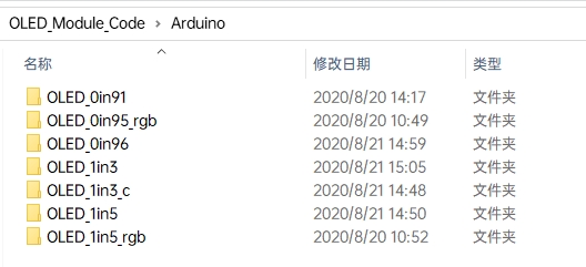
Download the demo and find the Arduino demo file directory.
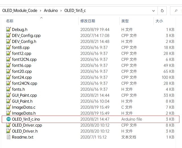
Use Arduino IDE to open the .ino file in the project folder of the corresponding model, recompile, and download the demo to your board.
For example, if you are using the 1.3inch OLED Module (C), open OLED_1in3_c.ino under the \Arduino\OLED_1in3_c directory
Software description
Download the demo on the Resources, and open the Arduino demo file directory, you can see the Arduino program for different models of OLED.
Choose the folder according to the LCD model you are using, and open the xxx.ino file. Take the 1.3-inch OLED Module (C) as an example: open OLED_1in3_c, then double-click OLED_1in3_c.ino to open the Arduino project.
The demo folder of each LCD model can be found in the following table:
0.91inch OLED Module
OLED_0in91
0.95inch RGB OLED (A)/(B)
OLED_0in95_rgb
0.96inch OLED (A)/(B)
OLED_0in96
0.96inch OLED Module (C)/(D)/(E)
OLED_0in96
1.27inch RGB OLED Module
OLED_1in27_rgb
1.3inch OLED (A)/(B)
OLED_1in3
1.3inch OLED Module (C)
OLED_1in3_c
1.32inch OLED Module
OLED_1in32
1.5inch OLED Module
OLED_1in5
1.5inch RGB OLED Module
OLED_1in5_rgb
Program description
Underlying hardware interface
Because the hardware platform and the internal implementation are different. If you need to know the internal implementation, you can see many definitions in the directory DEV_Config.c(.h)
Interface selection:
Data type:
Module initialization and exit processing:
Write and read GPIO:
SPI writes data:
IIC writes data:
The upper application
For the screen, if you need to draw pictures, display Chinese and English characters, display pictures, etc., you can use the upper application to do, and we provide some basic functions here about some graphics processing in the directory STM32\STM32F103RB\User\GUI\GUI_Paint.c(.h)

The character font which GUI dependent is in the directory STM32\STM32F103RB\User\Fonts

New Image Properties: Create a new image property, this property includes the image buffer name, width, height, flip Angle, color.
Set the clear screen function, usually call the clear function of OLED directly.
Set the drawing pixel function.
Select image buffer: the purpose of the selection is that you can create multiple image attributes, the image buffer can vary, and you can select each image you create.
Image Rotation: Set the selected image rotation Angle, preferably after Paint_SelectImage(), you can choose to rotate 0, 90, 180, or 270.
Image mirror flip: Set the mirror flip of the selected image. You can choose no mirror, horizontal mirror, vertical mirror, or image center mirror.
Set points of display position and color in the buffer: here is the core GUI function, processing points display position and color in the buffer.
Image buffer fill color: Fills the image buffer with a color, usually used to flash the screen into blank.
Draw points: In the image buffer, draw points on (Xpoint, Ypoint), you can choose the color, the size of the point, and the style of the point.
Line drawing: In the image buffer, line from (Xstart, Ystart) to (Xend, Yend), you can choose the color, line width, and line style.
Draw rectangle: In the image buffer, draw a rectangle from (Xstart, Ystart) to (Xend, Yend), you can choose the color, the width of the line, and whether to fill the inside of the rectangle.
Draw circle: In the image buffer, draw a circle of Radius with (X_Center Y_Center) as the center. You can choose the color, the width of the line, and whether to fill the inside of the circle.
Write Ascii character: In the image buffer, at (Xstart Ystart) as the left vertex, write an Ascii character, you can select Ascii visual character library, font foreground color, and font background color.
Write English string: In the image buffer, use (Xstart Ystart) as the left vertex, write a string of English characters, can choose Ascii visual character library, font foreground color, font background color.
Write Chinese string: in the image buffer, use (Xstart Ystart) as the left vertex, and write a string of Chinese characters, you can choose GB2312 encoding character font, font foreground color, and font background color.
Write numbers: In the image buffer, use (Xstart Ystart) as the left vertex, and write a string of numbers, you can choose Ascii visual character library, font foreground color, or font background color.
Display time: in the image buffer, use (Xstart Ystart) as the left vertex, display time, you can choose Ascii visual character font, font foreground color, font background color.
Last updated
Was this helpful?