1.5 inch LCD Display Module, IPS Panel SPI 262K colors
Product Link
Introduction
Provides demo for Raspberry Pi, STM32, Arduino, ESP32, Pico, and Jetson Nano.
Parameters
Operating voltage: 3V/5V
Communication interface: SPI (Please ensure that the supply voltage and logic voltage are consistent; otherwise, it may lead to malfunction.)
Screen type: IPS
Controller: NV3030B
Resolution: 240(H)RGB x 280(V)
Display size: 24.768 x 28.896 mm
Pixel pitch: 0.1032 (H) x 0.1032 (V) mm
Dimensions: 28.5 x 35 mm
Function Pin
Raspberry Pi
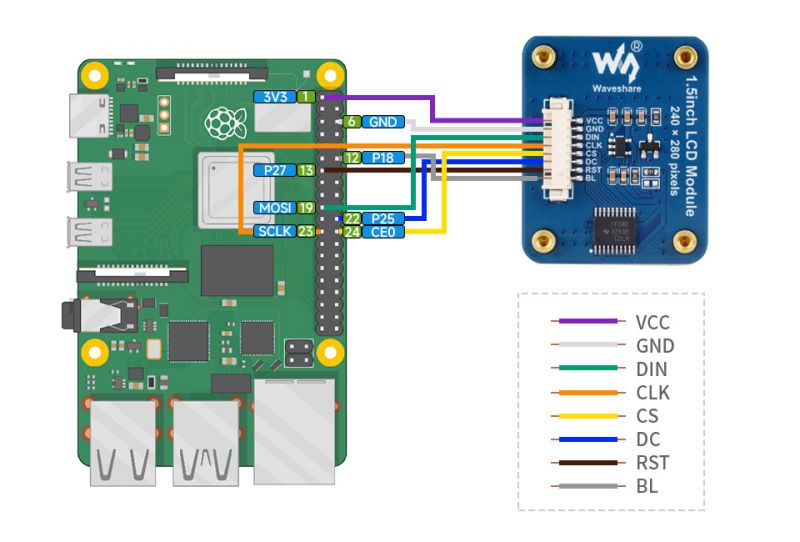
When connecting to the Raspberry Pi, select the GH1.25 8PIN cable to connect, please refer to the following table:
BCM2835 code
Board PIN
VCC
3.3V
3.3V
GND
GND
GND
DIN
MOSI
19
CLK
SCLK
23
CS
CE0
24
DC
25
22
RST
27
13
BL
18
12
The 1.5inch LCD uses the GH1.25 8PIN connector, connect it to the Raspberry Pi according to the above table: (Please connect it according to the pin definition table, the color of the wires in the picture is for reference only, the actual color shall prevail.)
STM32
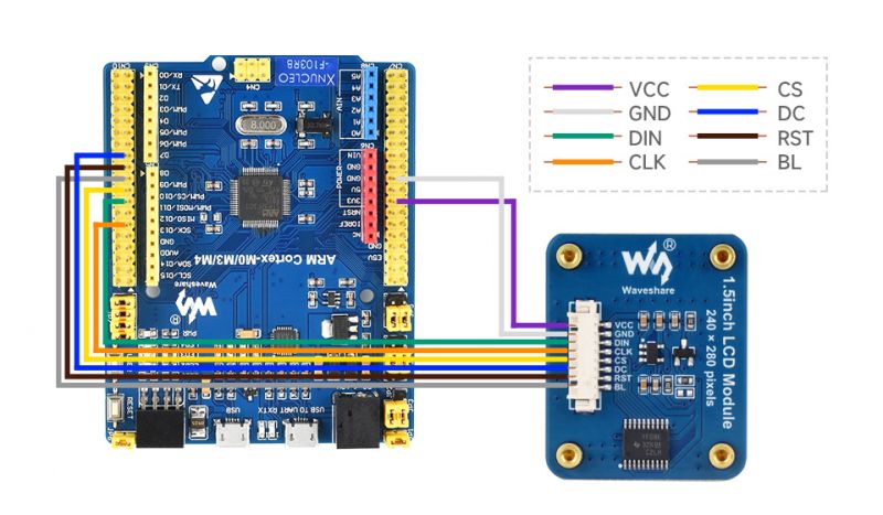
The demo we provided is based on STM32F103RBT6, and the connection method corresponds to the pins of STM32F103RBT6. If you need to port the demo, please connect it according to the actual pins:
VCC
3.3V
GND
GND
DIN
PA7
CLK
PA5
CS
PB6
DC
PA8
RST
PA9
BL
PC7
Take XNUCLEO-F103RB as an example, the connection is shown below:
Arduino
VCC
5V
GND
GND
DIN
D11
CLK
D13
CS
D10
DC
D7
RST
D8
BL
D9
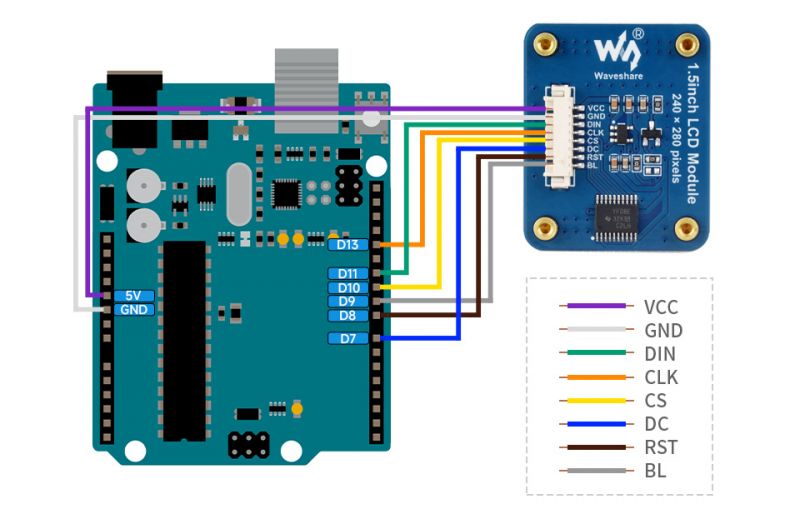
The connection diagram is as follows (click to enlarge):
ESP32
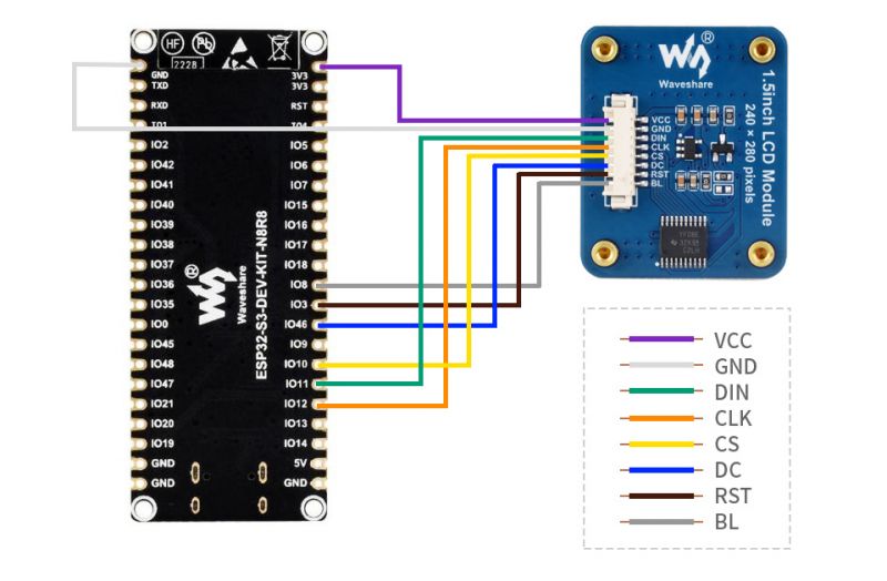
The demo we provided is based on ESP32-S3-WROOM-1-N8R8, and the connection also is based on ESP32-S3 pins. If you want to port the demo, please connect it according to the actual pin connection.
VCC
3V3
GND
GND
DIN
IO11
CLK
IO12
CS
IO10
DC
IO46
RST
IO3
BL
IO8
The connection diagram is as follows (click to enlarge):
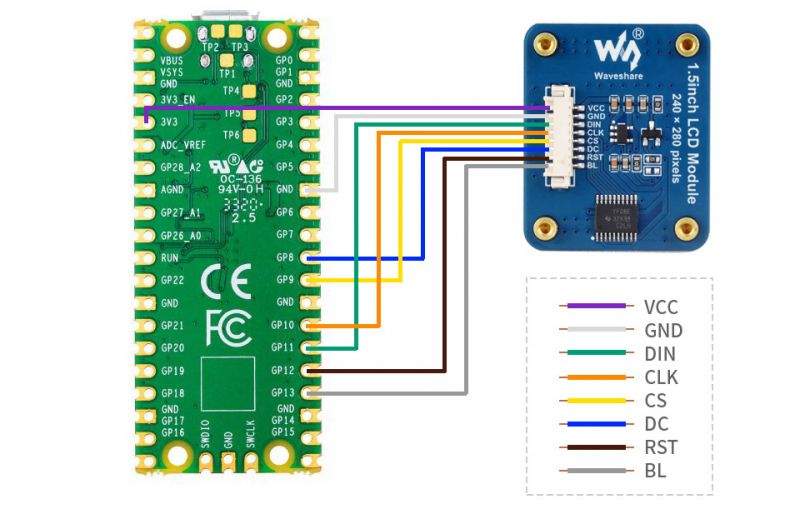
Pico
The demo we provided is based on Raspberry Pi Pico, and the connection also is based on ESP32-S3 pins. If you want to port the demo, please connect it according to the actual pin connection.
VCC
3.3V
GND
GND
DIN
GP11
CLK
GP10
CS
GP9
DC
GP8
RST
GP12
BL
GP13
Take Pico as the example as shown below:
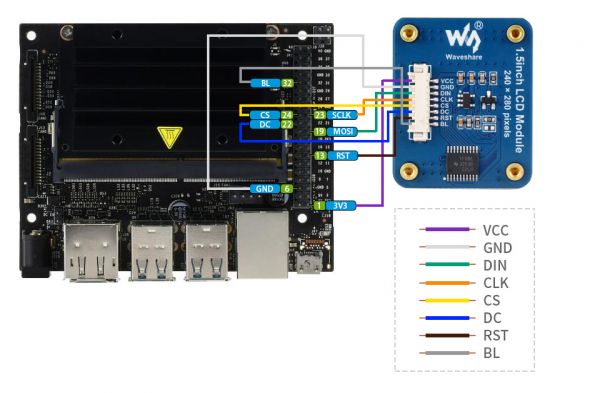
Jetson Nano
Connect the Jetson Nano with GH1.25 8PIN cable, please refer to the pinout table below.
BCM
Board
VCC
3.3V
3.3V
GND
GND
GND
DIN
MOSI
19
CLK
SCLK
23
CS
CE0
24
DC
25
22
RST
27
13
BL
12
32
The 1.5inch LCD uses a 1.25 8PIN connector, which can be connected to the Jetson Nano according to the above table: (Please connect according to the pin definition table, the color of the wires in the picture is for reference only, and the actual color shall prevail.)
LCD & Controller
The built-in controller used in this LCD is NV3030B, which is an LCD controller with 240 x RGB x 132 pixels, while the pixels of this LCD are 240(H)RGB x 280(V). Also, since the initialization control can be initialized to both horizontal and vertical screens, the LCD's internal RAM is not fully used. Looking over the datasheet, you can see that the controller supports 8-bit, 9-bit, 16-bit, and 18-bit input color formats per pixel, namely RGB444, RGB565, and RGB666 three color formats, this screen uses RGB565 format color format, which is also commonly used RGB Format. This LCD uses a four-wire SPI communication interface, which can greatly save the GPIO port, and the communication speed will be faster.
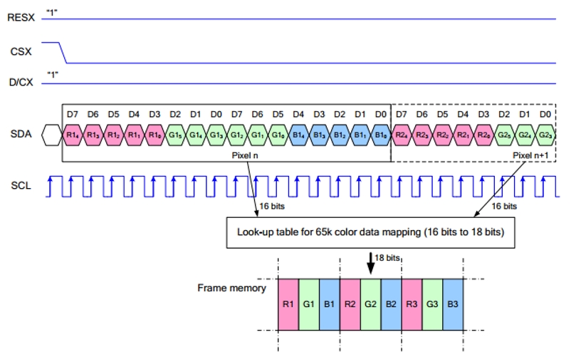
Communication Protocol
Note: The difference from the traditional SPI protocol is that the data line sent from the slave to the host is hidden because it only needs to be displayed. Please refer to Datasheet Page 66 for the table. RESX is reset, it is pulled low when the module is powered on, usually set to 1; CSX is the slave chip select, and the chip will be enabled only when CS is low. D/CX is the data/command control pin of the chip, when DC = 0, write command, when DC = 1, write data. SDA is the transmitted data, that is, RGB data; SCL is the SPI communication clock. For SPI communication, data is transmitted with timing, that is, the combination of clock phase (CPHA) and clock polarity (CPOL): The level of CPHA determines whether the serial synchronization clock is collected on the first clock transition edge or the second clock transition edge. When CPHA = 0, data acquisition is performed on the first transition edge; The level of CPOL determines the idle state level of the serial synchronous clock. CPOL = 0, which is a low level. As can be seen from the figure, when the first falling edge of SCLK starts to transmit data, 8-bit data is transmitted in one clock cycle, using SPI0, bit-by-bit transmission, high-order first, low-order last.
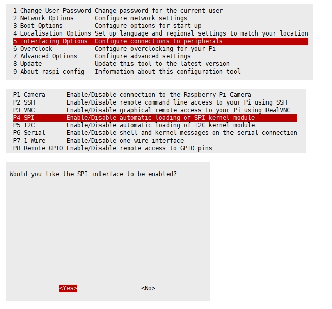
Working with RPI
Enable SPI interface
PS: If you are using the system of the Bullseye branch, you need to change "apt-get" to "apt", the system of the Bullseye branch only supports Python3.
Open terminal, use command to enter the configuration page
Reboot Raspberry Pi:
Please make sure that SPI interface was not used by other devices, you can check in the middle of /boot/config.txt.
Install Library
If you use bookworm system, only the lgpio library is available, bcm2835 and wiringPi libarary cannot be installed or used. Please note that the python library does not need to install, you can directly run the demo.
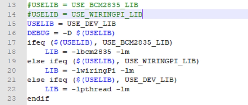
BCM2835
WiringPi
lgpio
Python
Download Examples
Open Raspberry Pi terminal and run the following command
Run the Demo
Please go into the RaspberryPi directory (demo codes) first and run the commands in terminal
C Codes
Re-compile the demo codes
The test program of all screens can be called directly by entering the corresponding size
Depending on the LCD, one of the following commands should be entered:
Python
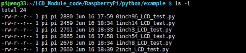
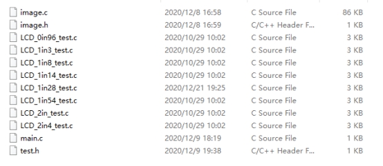
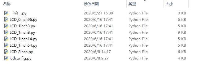
Enter the python demo directory and run the command ls -l
Test demos for all screens can be viewed, sorted by size:
Just run the demo corresponding to the screen, the demo supports python2/3
FBCP Porting
Framebuffer uses a video output device to drive a video display device from a memory buffer containing complete frame data. Simply put, a memory area is used to store the display content, and the display content can be changed by changing the data in the memory. There is an open source project on github: fbcp-ili9341. Compared with other fbcp projects, this project uses partial refresh and DMA to achieve a speed of up to 60fps.
Download Drivers
Method 1: Use a script (recommended)
Here we have written several scripts that allow users to quickly use fbcp and run corresponding commands according to their screens. If you use a script and do not need to modify it, you can ignore the second method below. Note: The script will replace the corresponding /boot/config.txt and /etc/rc.local and restart, if the user needs, please back up the relevant files in advance
Method 2: Manual Configuration
Environment Configuration
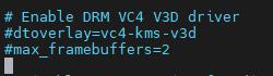
Raspberry Pi's vc4-kms-v3d will cause fbcp to fail, so we need to close vc4-kms-v3d before installing in fbcp
Just block the statement corresponding to the picture below: A reboot is then required.
Compile And Run
Replace it by yourself according to the LCD Module you use, above cmake [options] ..
Set up to Start Automatically

Add fbcp& before exit 0. Note that you must add "&" to run in the background, otherwise the system may not be able to start.
Set the Display Resolution
Set the user interface display size in the /boot/config.txt file.
Then add the following lines at the end of the config.txt.
Replace the above hdmi_cvt=[options] according to the LCD Module you are using.
And then reboot the system
After rebooting the system, the Raspberry Pi OS user interface will be displayed.

API (Options for C/Python)
Raspberry Pi series can all share a common set of programs, because they are embedded systems, compatibility is stronger. The demo is divided into the bottom hardware interface, the middle layer LCD driver, and the upper layer application;
C
Hardware Interface
We have carried out the low-level encapsulation, if you need to know the internal implementation can go to the corresponding directory to check, for the reason that the hardware platform and the internal implementation are different. You can open DEV_Config.c(.h) to see definitions, which in the directory RaspberryPi\c\lib\Config.
Data type
Module initialization and exit processing.
GPIO read and write:
SPI write data
Upper Application
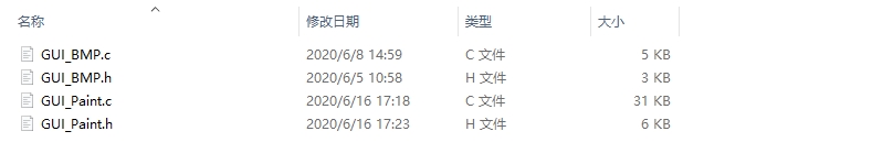
If you need to draw pictures, display Chinese and English characters, display pictures, etc., we provide some basic functions here about some graphics processing in the directory RaspberryPi\c\lib\GUI\GUI_Paint.c(.h). The fonts can be found in RaspberryPi\c\lib\Fonts directory.
New Image Properties: Create a new image buffer, this property includes the image buffer name, width, height, flip Angle, and color.
Select image buffer: The purpose of the selection is that you can create multiple image attributes, there can be multiple image buffers, and you can select each image you create.
Image Rotation: Set the rotation Angle of the selected image, preferably after Paint_SelectImage(), you can choose to rotate 0, 90, 180, 270.
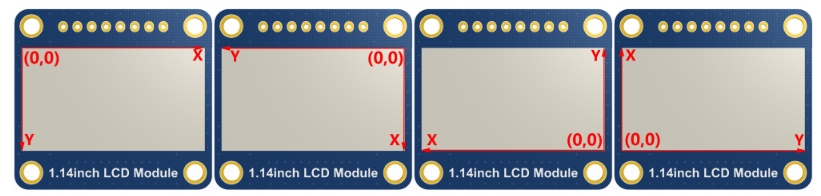
Image mirror flip: Set the mirror flip of the selected image. You can choose no mirror, horizontal mirror, vertical mirror, or image center mirror.
Set points of the display position and color in the buffer: here is the core GUI function, processing points display position and color in the buffer.
Image buffer fill color: Fills the image buffer with a color, usually used to flash the screen into blank.
The fill color of a certain window in the image buffer: the image buffer part of the window filled with a certain color, usually used to fresh the screen into blank, often used for time display, fresh the last second of the screen.
Draw point: In the image buffer, draw points on (Xpoint, Ypoint), you can choose the color, the size of the point, and the style of the point.
Draw the line: In the image buffer, draw a line from (Xstart, Ystart) to (Xend, Yend), you can choose the color, the width, and the style of the line.
Draw a rectangle: In the image buffer, draw a rectangle from (Xstart, Ystart) to (Xend, Yend), you can choose the color, the width of the line, and whether to fill the inside of the rectangle.
Draw circle: In the image buffer, draw a circle of Radius with (X_Center Y_Center) as the center. You can choose the color, the width of the line, and whether to fill the inside of the circle.
Write Ascii character: In the image buffer, use (Xstart Ystart) as the left vertex, and write an Ascii character, you can select Ascii visual character library, font foreground color, and font background color.
Write English string: In the image buffer, use (Xstart Ystart) as the left vertex, and write a string of English characters, you can choose Ascii visual character library, font foreground color, or font background color.
Write Chinese string: in the image buffer, use (Xstart Ystart) as the left vertex, and write a string of Chinese characters, you can choose character font, font foreground color, and font background color of the GB2312 encoding.
Write numbers: In the image buffer, use (Xstart Ystart) as the left vertex, and write a string of numbers, you can choose Ascii visual character library, font foreground color, or font background color.
Write a series of numbers with decimals in the image buffer, with (Xstart Ystart) as the top-left vertex. You can choose from an ASCII visual character library, font foreground color, and font background color.
Display time: in the image buffer, use (Xstart Ystart) as the left vertex, For display time, you can choose Ascii visual character font, font foreground color, or font background color.;
Read the local bmp image and write it to the cache
For Linux operating systems such as Raspberry Pi, you can read and write pictures For Raspberry Pi, in the directory: RaspberryPi\c\lib\GUI\GUI_BMPfile.c(.h)
User Test Code
The first three chapters introduce the classic Linux three-layer code structure, here is a little bit about the user test code For Raspberry Pi, in the directory: RaspberryPi\c\examples, for all the test code;
If you need to run the 0.96-inch LCD test program, you need to add 0.96 as a parameter when running the mian program. Re-execute in Linux command mode as follows:
Python(for Raspberry Pi)
Works with python and python3. Python is not as complicated as C. Raspberry Pi: RaspberryPi\python\lib\
lcdconfig.py
Module initialization and exit processing.
GPIO read and write:
SPI write data.
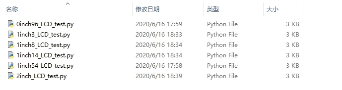
xxx_LCD_test.py (xxx indicates the size, if it is a 0.96inch LCD, it is 0inch96_LCD_test.py, and so on)
python is in the following directory: Raspberry Pi: RaspberryPi\python\examples\
If your Python version is python2 and you need to run the 0.96inch LCD test program, re-execute it as follows in Linux command mode:
If your Python version is python3 and you need to run the 0.96inch LCD test program, re-execute the following in Linux command mode:
About Rotation Settings
If you need to set the screen rotation in the Python program, you can set it by the statement im_r= image1.rotate(270).
Rotation effect, take 1.54 as an example, the order is 0°, 90°, 180°, 270°

GUI Functions
Python has an image library PIL official library link, it does not need to write code from the logical layer like C and can directly call the image library for image processing. The following will take a 1.54-inch LCD as an example, we provide a brief description of the demo.
It needs to use the image library and install the library.
And then import the library:
Among them, Image is the basic library, ImageDraw is the drawing function, and ImageFont is the text function.
Define an image cache to facilitate drawing, writing, and other functions on the picture.
The first parameter defines the color depth of the image, which is defined as RGB indicating RGB888 colorful image. The second parameter is a tuple that defines the width and height of the image. The third parameter defines the default color of the buffer, which is defined as "WHITE".
Create a drawing object based on Image1 on which all drawing operations will be performed on here.
Draw a line.
The first parameter is a four-element tuple starting at (20, 10) and ending at (70, 60). Draw a line. Fill ="RED" means the color of the line is red. width =1 indicates the line width is one pixel.
Draw a rectangle.
The first parameter is a tuple of four elements. (20,10) is the coordinate value in the upper left corner of the rectangle, and (70,60) is the coordinate value in the lower right corner of the rectangle. Fill =" WHITE" means BLACK inside, and outline="BLUE" means the color of the outline is blue.
Draw a circle.
Draw an inscribed circle in the square, the first parameter is a tuple of 4 elements, with (150, 15) as the upper left corner vertex of the square, (190, 55) as the lower right corner vertex of the square, specifying the level median line of the rectangular frame is the angle of 0 degrees, and this angle becomes larger clockwise. The second parameter indicates the starting angle, the third parameter indicates the ending angle and fill =(0,255,0) indicates that the color of the line is green. If the figure is not square according to the coordination, you will get an ellipse. Besides the arc function, you can also use the chord function for drawing a solid circle.
It is the drawing of the ellipse, the first parameter specifies the string of the circle tangent rectangle, fill = (0,255,0) that the internal fill color is green, if the ellipse tangent matrix is a square, the ellipse is a circle.
Character.
The ImageFont module needs to be imported and instantiated:
To have a better visual experience, here is the use of free fonts from the web, if other font files with the suffix ttf are also supported. Note: Each font contains different characters; if some characters can not be displayed, it is recommended to use the font according to the encoding set to use! Write English characters can be used directly, write Chinese, as its encoding is GB2312 so you need to add "u" in front:
The first parameter is a 2-element tuple with (40, 50) as the left vertex, Font2, and "fill" as the font color. You can just let fill = "WHITE" as the values for the regular colors are already defined, but of course, you can use fill = (128,255,128) with the values corresponding to the three RGB colors in parentheses so that you will be able to control exactly the color you want. The second sentence displays "微雪电子" (Waveshare Electronics), using Font3 with a white font color.
Read local pictures.
The parameter is the image path.
Other functions.
Python's image library is very powerful, if you need to implement more, you can learn on the website http://effbot.org/imagingbook pil.
STM32 Software Description
Software Description
The demo is developed based on the HAL library. Download the demo, find the STM32 program file directory, and open the LCD_demo.uvprojx in the STM32\STM32F103RBT6\MDK-ARM directory to check the program.

Open main.c, you can see all the test programs, remove the comments in front of the test programs on the corresponding screen, and recompile and download.

Program Description
Underlying Hardware Interface
Data type
Module initialization and exit processing
Write and read GPIO
SPI writes data
Upper Application
For the screen, if you need to draw pictures, display Chinese and English characters, display pictures, etc., you can use the upper application to do so, and we provide some basic functions here about some graphics processing in the directory STM32\STM32F103RB\User\GUI_DEV\GUI_Paint.c(.h) Note: Because of the size of the internal RAM of STM32 and Arduino, the GUI is directly written to the RAM of the LCD. The character font on which GUI dependent is in the directory STM32\STM32F103RB\User\Fonts


New Image Properties: Create a new image property, this property includes the image buffer name, width, height, flip Angle, and color.
Set the clear screen function, usually call the clear function of LCD directly.
Set the drawing pixel function
Select image buffer: the purpose of the selection is that you can create multiple image attributes, an image buffer can exist multiple, and you can select each image you create.
Image Rotation: Set the selected image rotation Angle, preferably after Paint_SelectImage(), you can choose to rotate 0, 90, 180, 270.
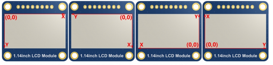
Image mirror flip: Set the mirror flip of the selected image. You can choose no mirror, horizontal mirror, vertical mirror, or image center mirror.
Set points of display position and color in the buffer: here is the core GUI function, processing points display position and color in the buffer.
Image buffer fill color: Fills the image buffer with a color, usually used to flash the screen into blank.
Image buffer part of the window filling color: the image buffer part of the window filled with a certain color, generally as a window whitewashing function, often used for time display, whitewashing on a second
Draw points: In the image buffer, draw points on (Xpoint, Ypoint), you can choose the color, the size of the point, and the style of the point.
Line drawing: In the image buffer, line from (Xstart, Ystart) to (Xend, Yend), you can choose the color, line width, and line style.
Draw a rectangle: In the image buffer, draw a rectangle from (Xstart, Ystart) to (Xend, Yend), you can choose the color, the width of the line, and whether to fill the inside of the rectangle.
Draw circle: In the image buffer, draw a circle of Radius with (X_Center Y_Center) as the center. You can choose the color, the width of the line, and whether to fill the inside of the circle.
Write Ascii character: In the image buffer, at (Xstart Ystart) as the left vertex, write an Ascii character, you can select the Ascii visual character library, font foreground color, and font background color.
Write English string: In the image buffer, use (Xstart Ystart) as the left vertex, write a string of English characters, can choose Ascii visual character library, font foreground color, font background color.
Write Chinese string: in the image buffer, use (Xstart Ystart) as the left vertex, and write a string of Chinese characters, you can choose GB2312 encoding character font, font foreground color, and font background color.
Write numbers: In the image buffer, use (Xstart Ystart) as the left vertex, and write a string of numbers, you can choose Ascii visual character library, font foreground color, or font background color.
Write a series of numbers with decimals in the image buffer, with (Xstart Ystart) as the top-left vertex. You can choose from an ASCII visual character library, font foreground color, and font background color.
Display time: in the image buffer, use (Xstart Ystart) as the left vertex to display time, you can choose Ascii visual character font, font foreground color, or font background color.
Arduino Software Description
Note: The examples were tested on the Arduino UNO R3 PLUS. If using a different model of Arduino, ensure that the connected pins are correct and whether it's possible to adjust the operating voltage and logic level to 3.3V.
Arduino IDE Installation Tutorial
Run the Demo
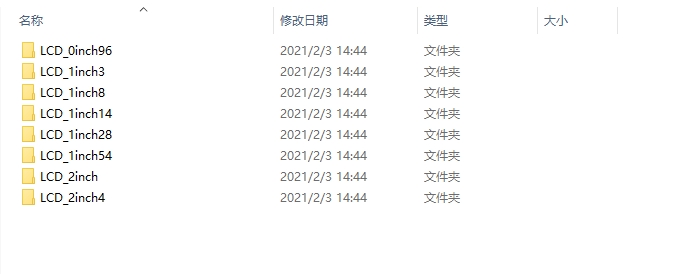
Please open the demo corresponding to the LCD. You can see the test demos for all screen sizes, categorized by size. For example, a 1.54-inch LCD Module. Open the LCD_1inch54 folder and run the LCD_1inch54.ino file. Open the program, and select the development board model Arduino UNO.
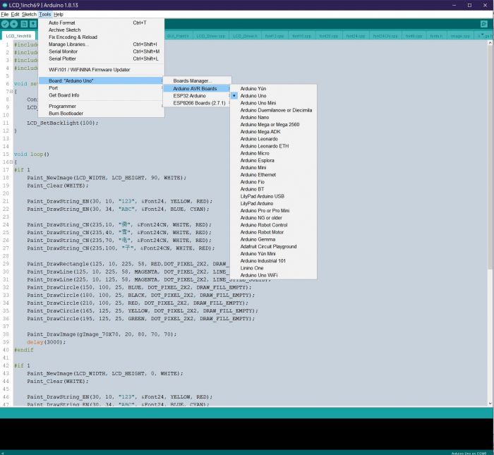
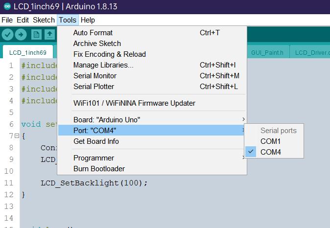
Choose the corresponding COM port.
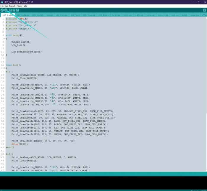
Then click to compile and download.
Demo Remarks
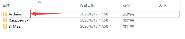
File Introduction
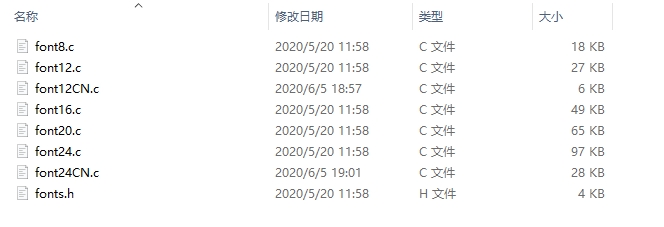
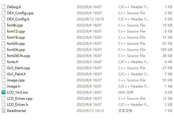
Take ESP32-S3 controlling 1.5inch LCD as an example, open the ESP32\LCD_1inch5 directory: Among them: LCD_1inch5.ino: Open it using the Arduino IDE. LCD_Driver.cpp(.h): The driver demo for the LCD screen. DEV_Config.cpp(.h): Hardware interface definitions, encapsulating pin level reading/writing, SPI data transmission, and pin initialization. font8.cpp, font12.cpp, font16.cpp, font20.cpp, font24.cpp, font24CN.cpp, fonts.h: Font modules for different character sizes. image.cpp(.h): Contains image data. Use Img2Lcd (available for download in the development resources) to convert any BMP image into a 16-bit true-color image array. The program is divided into the hardware interface at the bottom, the LCD screen driver in the middle, and the upper-layer applications.
Hardware Low-Level Interface
The DEV_Config.cpp(.h) files define hardware interfaces and encapsulate functions for reading/writing pin levels, delays, and SPI data transmission.
Writing Pin Levels
The first parameter represents the pin, and the second parameter indicates the logic level.
Reading Pin Levels
The parameter is the PIN, and the return value is the read logic level.
Delay
This function provides millisecond-level delay.
SPI Data Output
The parameter is a char type, occupying 8 bits.
Upper Application
If you need to draw pictures, display Chinese and English characters, display pictures, etc., we provide some basic functions here about some graphics processing in the directory GUI_Paint.c(.h). Note: As the limited RAM of STM32 and Arduino, GUI adopts the direct writing to the LCD's RAM.
The fonts can be found in RaspberryPi\c\lib\Fonts directory.
New Image Properties: Create a new image buffer, this property includes the image buffer name, width, height, flip Angle, and color.
Select image buffer: The purpose of the selection is that you can create multiple image attributes, there can be multiple image buffers, and you can select each image you create.
Image Rotation: Set the rotation Angle of the selected image, preferably after Paint_SelectImage(), you can choose to rotate 0, 90, 180, 270.
Image mirror flip: Set the mirror flip of the selected image. You can choose no mirror, horizontal mirror, vertical mirror, or image center mirror.
Set points of the display position and color in the buffer: here is the core GUI function, processing points display position and color in the buffer.
Image buffer fill color: Fills the image buffer with a color, usually used to flash the screen into blank.
The fill color of a certain window in the image buffer: the image buffer part of the window filled with a certain color, usually used to fresh the screen into blank, often used for time display, fresh the last second of the screen.
Draw point: In the image buffer, draw points on (Xpoint, Ypoint), you can choose the color, the size of the point, and the style of the point.
Draw the line: In the image buffer, draw a line from (Xstart, Ystart) to (Xend, Yend), you can choose the color, the width, and the style of the line.
Draw a rectangle: In the image buffer, draw a rectangle from (Xstart, Ystart) to (Xend, Yend), you can choose the color, the width of the line, and whether to fill the inside of the rectangle.
Draw circle: In the image buffer, draw a circle of Radius with (X_Center Y_Center) as the center. You can choose the color, the width of the line, and whether to fill the inside of the circle.
Write Ascii character: In the image buffer, use (Xstart Ystart) as the left vertex, and write an Ascii character, you can select Ascii visual character library, font foreground color, and font background color.
Write English string: In the image buffer, use (Xstart Ystart) as the left vertex, and write a string of English characters, you can choose Ascii visual character library, font foreground color, or font background color.
Write Chinese string: in the image buffer, use (Xstart Ystart) as the left vertex, and write a string of Chinese characters, you can choose character font, font foreground color, and font background color of the GB2312 encoding.
Write numbers: In the image buffer, use (Xstart Ystart) as the left vertex, and write a string of numbers, you can choose Ascii visual character library, font foreground color, or font background color.
Write a series of numbers with decimals in the image buffer, with (Xstart Ystart) as the top-left vertex. You can choose from an ASCII visual character library, font foreground color, and font background color.
Display time: in the image buffer, use (Xstart Ystart) as the left vertex, For display time, you can choose Ascii visual character font, font foreground color, or font background color.;
Display image: use (Xstart Ystart) as the left vertex, and display an image with the width of W_Image and the height of H_Image.
Pico Software Description
Hardware Connection
The demo we provided is based on Pico, and the connection method also corresponds to the Pico pins. If you want to port the demo, please connect it corresponding to the actual pins.
VCC
3.3V
GND
GND
DIN
GP11
CLK
GP10
CS
GP9
DC
GP8
RST
GP12
BL
GP13
IDE Installation
Run the Demo
Demo Remarks
Bottom Layer Hardware Interface
SPI write command:
SPI write data:
Backlight adjustment:
Display initialization:
Display pixel point:
ESP Software Description
Note: The example demos were tested on the ESP32-S3. If using a different model of ESP32, ensure that the connected pins are correct.
Arduino IDE Installation Guide
Run the demo
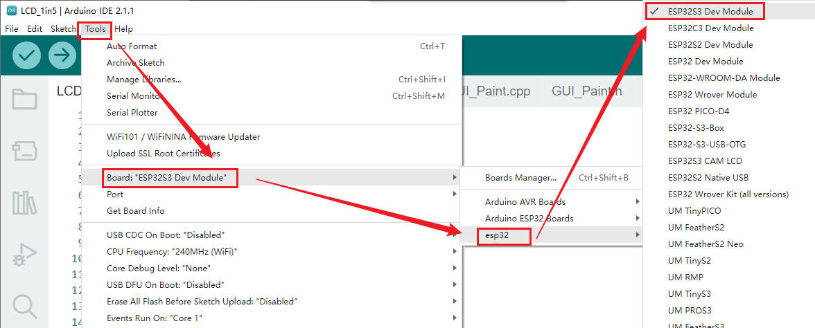
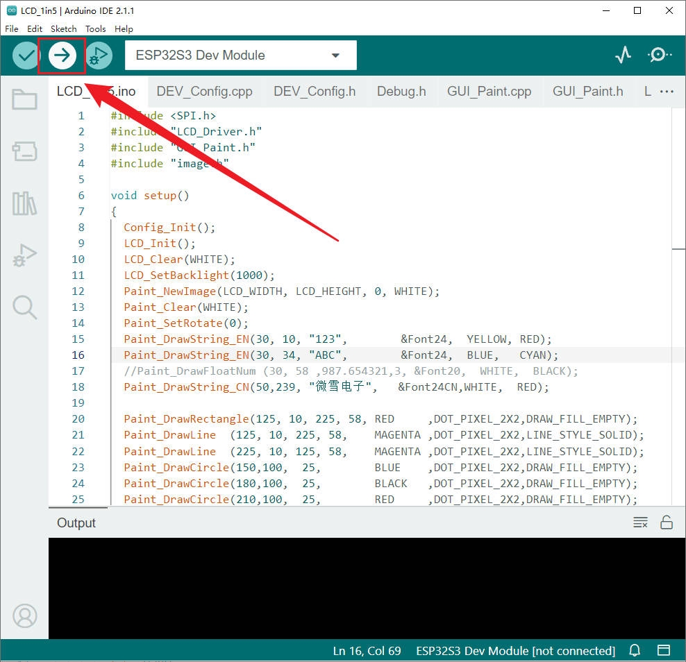
Download the demo, and extract it. The path of ESP32 demo is ~/ESP32/… Please open the demo corresponding to the LCD model: It is possible to view all the test demos for screen sizes, categorized by size: For example, a 1.5-inch LCD Module. Open the LCD_1inch5 folder and run the LCD_1inch5.ino file. Enter the program, and select "ESP32S3 Dev Module".

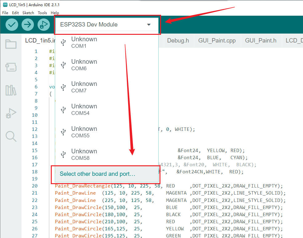
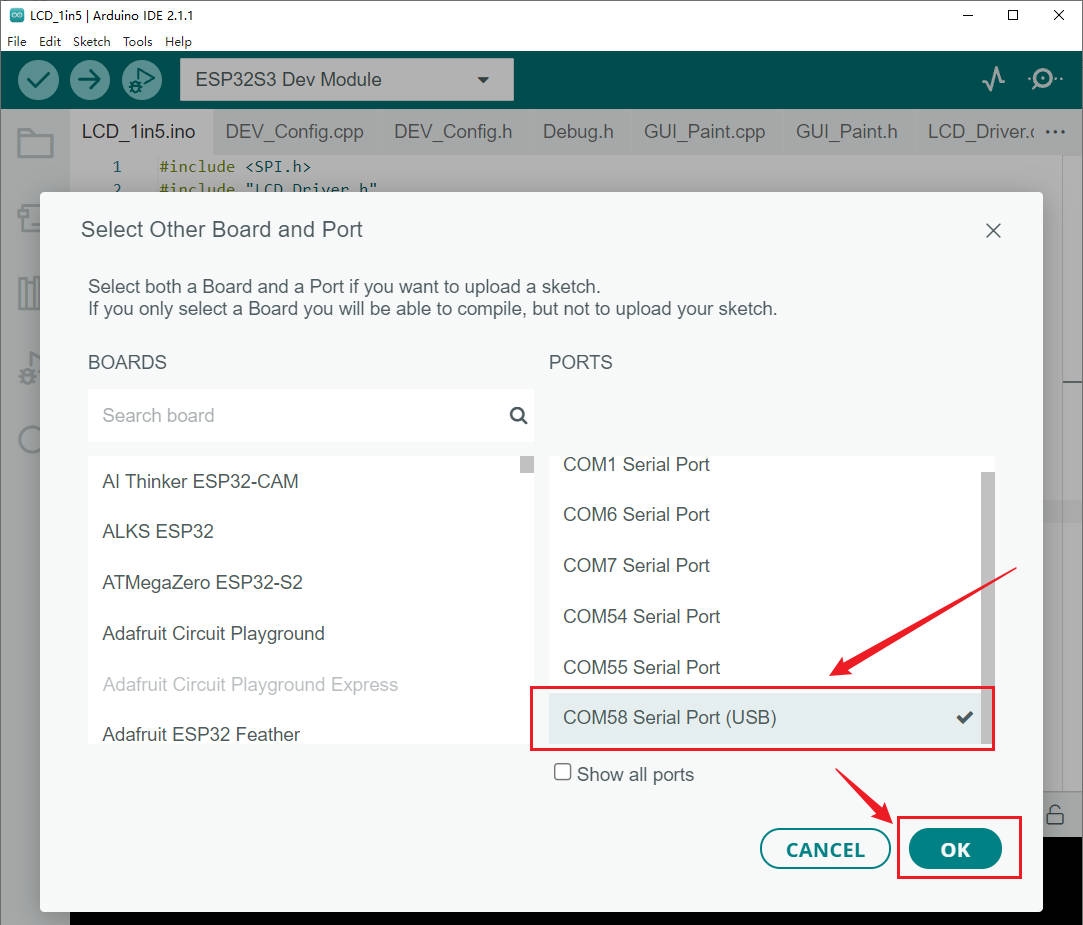
Select the corresponding COM port:
Click to compile and download:
Demo Remarks
File Introduction
Take ESP32-S3 controlling 1.5inch LCD as an example, open the ESP32\LCD_1inch5 directory: Among them: LCD_1inch5.ino: Open it using the Arduino IDE. LCD_Driver.cpp(.h): The driver demo for the LCD screen. DEV_Config.cpp(.h): Hardware interface definitions, encapsulating pin level reading/writing, SPI data transmission, and pin initialization. font8.cpp, font12.cpp, font16.cpp, font20.cpp, font24.cpp, font24CN.cpp, fonts.h: Font modules for different character sizes. image.cpp(.h): Contains image data. Use Img2Lcd (available for download in the development resources) to convert any BMP image into a 16-bit true-color image array. The program is divided into the hardware interface at the bottom, the LCD screen driver in the middle, and the upper-layer applications.
Bottom Layer Hardware Interface
The hardware interface is defined in the two files DEV_Config.cpp(.h) and encapsulates the functions to read and write pin levels, delays, SPI transfers, and so on.
Write Pin Level
The first parameter is the pin, and the second parameter is the level.
Read Pin Level
The parameter is the pin, and the returned value is the level of the actual pin.
Delay
Millisecond level delay.
SPI Output Data
The parameter is char type, 8 bits.
The Upper Application
For the screen, if you need to draw, display Chinese and English characters, display pictures, and so on, which is performed by the upper application. As most users have asked about the graphics processing, we provide some basic functions - GUI_Paint.c(.h). Note: As the internal RAM size of the ESP32 and Arduino is limited, the GUI is used to write directly into the LCD's RAM. The fonts used by the GUI all depend on the font*.cpp(h) file under the same file.


New Image Properties: Create a new image property, this property includes the image buffer name, width, height, flip Angle, and color.
Set the clear screen function, usually call the clear function of LCD directly.
Set the drawing pixel function
Select image buffer: the purpose of the selection is that you can create multiple image attributes, image buffer can exist multiple, you can select each image you create.
Image Rotation: Set the selected image rotation Angle, preferably after Paint_SelectImage(), you can choose to rotate 0, 90, 180, or 270.
Image mirror flip: Set the mirror flip of the selected image. You can choose no mirror, horizontal mirror, vertical mirror, or image center mirror.
Set points of display position and color in the buffer: here is the core GUI function, processing points display position and color in the buffer.
Image buffer fill color: Fills the image buffer with a color, usually used to flash the screen into blank.
Image buffer part of the window filling color: the image buffer part of the window filled with a certain color, generally as a window whitewashing function, often used for time display, whitewashing on a second
Draw points: In the image buffer, draw points on (Xpoint, Ypoint), you can choose the color, the size of the point, and the style of the point.
Line drawing: In the image buffer, line from (Xstart, Ystart) to (Xend, Yend), you can choose the color, line width, and line style.
Draw rectangle: In the image buffer, draw a rectangle from (Xstart, Ystart) to (Xend, Yend), you can choose the color, the width of the line, and whether to fill the inside of the rectangle.
Draw circle: In the image buffer, draw a circle of Radius with (X_Center Y_Center) as the center. You can choose the color, the width of the line, and whether to fill the inside of the circle.
Write Ascii character: In the image buffer, at (Xstart Ystart) as the left vertex, write an Ascii character, you can select the Ascii visual character library, font foreground color, and font background color.
Write English string: In the image buffer, use (Xstart Ystart) as the left vertex, write a string of English characters, can choose Ascii visual character library, font foreground color, font background color.
Write Chinese string: in the image buffer, use (Xstart Ystart) as the left vertex, and write a string of Chinese characters, you can choose GB2312 encoding character font, font foreground color, and font background color.
Write numbers: In the image buffer, use (Xstart Ystart) as the left vertex, and write a string of numbers, you can choose Ascii visual character library, font foreground color, or font background color.
Write Numbers with Decimals: Display a series of numbers with decimal points starting at the (Xstart, Ystart) coordinates as the top-left vertex. This function allows the selection of an ASCII visual character library, font foreground color, and font background color.
Display time: in the image buffer, use (Xstart Ystart) as the left vertex. For display time, you can choose Ascii visual character font, font foreground color, or font background color.
Display Image: Show an image with a width of W_Image and height of H_Image, starting at the (Xstart, Ystart) coordinates as the top-left vertex.
Jetson Nano User Guide
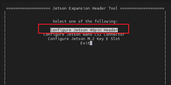
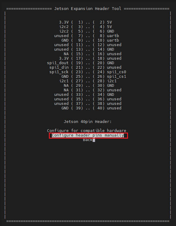
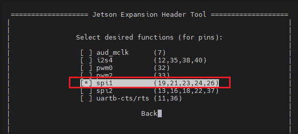
Enable SPI Interface
Open the Jetson Nano terminal, and click here to see how to Open SPI:
Library Installation
Install Python function library:
Download & Test the Demo
Open the Jetson Nano terminal and execute:
Run the Test Demo
Please run the following commands on the Jetson Nano directory, or it can not be indexed in the directory.
Python
Go to the Python demo directory and run the command ls -l.
You can view the test programs for all screens, categorized by size:
Just run the program for the corresponding screen, the program supports python2/3.
API
Python (for Jetson Nano)
Works with python and python3. Jetson Nano: Jetson Nano\python\lib\
lcdconfig.py
Module initialization and exit processing.
GPIO read and write:
SPI write data.
xxx_LCD_test.py (xxx indicates the size, if it is a 0.96inch LCD, it is 0inch96_LCD_test.py, and so on)
python is in the following directory: Jetson Nano:Jetson Nano\python\examples\
If your Python version is python2 and you need to run the 0.96inch LCD test program, re-execute it as follows in Linux command mode:
If your Python version is python3 and you need to run the 0.96inch LCD test program, re-execute the following in Linux command mode:
About Rotation Settings
If you need to set the screen rotation in the Python program, you can set it by the statement im_r= image1.rotate(270).
Rotation effect, take 1.54 as an example, the order is 0°, 90°, 180°, 270°
GUI Functions
Python has an image library PIL official library link, it does not need to write code from the logical layer like C and can directly call the image library for image processing. The following will take a 1.54-inch LCD as an example, we provide a brief description of the demo.
It needs to use the image library and install the library.
And then import the library:
Among them, Image is the basic library, ImageDraw is the drawing function, and ImageFont is the text function.
Define an image cache to facilitate drawing, writing, and other functions on the picture.
The first parameter defines the color depth of the image, which is defined as RGB indicating RGB888 colorful image. The second parameter is a tuple that defines the width and height of the image. The third parameter defines the default color of the buffer, which is defined as "WHITE".
Create a drawing object based on Image1 on which all drawing operations will be performed on here.
Draw a line.
The first parameter is a four-element tuple starting at (20, 10) and ending at (70, 60). Draw a line. Fill ="RED" means the color of the line is red. width =1 indicates the line width is one pixel.
Draw a rectangle.
The first parameter is a tuple of four elements. (20,10) is the coordinate value in the upper left corner of the rectangle, and (70,60) is the coordinate value in the lower right corner of the rectangle. Fill =" WHITE" means BLACK inside, and outline="BLUE" means the color of the outline is blue.
Draw a circle.
Draw an inscribed circle in the square, the first parameter is a tuple of 4 elements, with (150, 15) as the upper left corner vertex of the square, (190, 55) as the lower right corner vertex of the square, specifying the level median line of the rectangular frame is the angle of 0 degrees, and this angle becomes larger clockwise. The second parameter indicates the starting angle, the third parameter indicates the ending angle and fill =(0,255,0) indicates that the color of the line is green. If the figure is not square according to the coordination, you will get an ellipse. Besides the arc function, you can also use the chord function for drawing a solid circle.
It is the drawing of the ellipse, the first parameter specifies the string of the circle tangent rectangle, fill = (0,255,0) that the internal fill color is green, if the ellipse tangent matrix is a square, the ellipse is a circle.
Character.
The ImageFont module needs to be imported and instantiated:
To have a better visual experience, here is the use of free fonts from the web, if other font files with the suffix ttf are also supported. Note: Each font contains different characters; if some characters can not be displayed, it is recommended to use the font according to the encoding set to use! Write English characters can be used directly, write Chinese, as its encoding is GB2312 so you need to add "u" in front:
The first parameter is a 2-element tuple with (40, 50) as the left vertex, Font2, and "fill" as the font color. You can just let fill = "WHITE" as the values for the regular colors are already defined, but of course, you can use fill = (128,255,128) with the values corresponding to the three RGB colors in parentheses so that you will be able to control exactly the color you want. The second sentence displays "微雪电子" (Waveshare Electronics), using Font3 with a white font color.
Read local pictures.
The parameter is the image path.
Other functions.
Python's image library is very powerful, if you need to implement more, you can learn on the website http://effbot.org/imagingbook pil.
Resource
Drawing
Document
Demo
Software
FAQ
Last updated
Was this helpful?