Seeed Studio XIAO nRF52840 Sense TinyML/TensorFlow Lite
Product Link
Introduction
As the first wireless product in the Seeed Studio XIAO family, Seeed Studio XIAO nRF52840 is equipped with a powerful Nordic nRF52840 MCU which integrates Bluetooth 5.0 connectivity. Meanwhile, it has a small and exquisite form-factor which can be used for wearable devices and Internet of Things projects. The single-sided surface-mountable design and the onboard Bluetooth antenna can greatly facilitate the rapid deployment of IoT projects.
In addition, there is an advanced version of this board, Seeed Studio XIAO nRF52840 Sense. It is integrated with two extra onboard sensors. One of them is a Pulse Density Modulation (PDM) Digital Microphone. It can receive audio data in real-time which allows it to be used for audio recognition. The other one is a 6-axis Inertial Measurement Unit (IMU), this IMU can be very useful in TinyML projects like gesture recognition. These onboard sensors provide a great convenience for users while the board is ultra-small.
Compared to Seeed Studio XIAO RP2040, Seeed Studio XIAO nRF52840 contains richer interfaces. The first thing to note is that the Near Field Communication (NFC) interface is functional on the board. Secondly, there is a tiny reset button on the side of the Type-C interface. On the other side, there is a 3-in-one LED (User LED) along with a Charge LED to indicate the charging status when a battery is connected. There are 11 digital I/O that can be used as PWM pins and 6 analog I/O that can be used as ADC pins. It supports all three common serial interfaces such as UART, I2C, and SPI. Same as Seeed Studio XIAO RP2040, it has an onboard 2 MB flash which means it can also be programmed using Arduino, MicroPython, CircuitPython, or other programming languages.
Features
Powerful wireless capabilities: Bluetooth 5.0 with onboard antenna
Powerful CPU: Nordic nRF52840, ARM® Cortex®-M4 32-bit processor with FPU, 64 MHz
Ultra-Low Power: Standby power consumption is less than 5μA
Battery charging chip: Supports lithium battery charge and discharge management
Onboard 2 MB flash
Onboard PDM microphone (only in Seeed Studio XIAO nRF52840 Sense)
Onboard 6-axis LSM6DS3TR-C IMU (only in Seeed Studio XIAO nRF52840 Sense)
Ultra Small Size: 21 x 17.8mm, Seeed Studio XIAO series classic form-factor for wearable devices
Rich interfaces: 1xUART, 1xI2C, 1xSPI, 1xNFC, 1xSWD, 11xGPIO(PWM), 6xADC
Single-sided components, surface mounting design
Specifications comparison
Processor
SAMD21 M0+@48MHz
RP2040 Dual-core M0+@133Mhz
nRF52840 M4F@64MHz
nRF52840 M4F@64MHz
Wireless Connectivity
N/A
N/A
Bluetooth 5.0/BLE/NFC
Bluetooth 5.0/BLE/NFC
Memory
32 KB SRAM 256KB FLASH
264 KB SRAM 2MB onboard Flash
256 KB RAM, 1MB Flash 2MB onboard Flash
256 KB RAM,1MB Flash 2MB onboard Flash
Built-in Sensors
N/A
N/A
N/A
6 DOF IMU (LSM6DS3TR-C), PDM Microphone
Interfaces
I2C/UART/SPI
I2C/UART/SPI
I2C/UART/SPI
I2C/UART/SPI
PWM/Analog Pins
11/11
11/4
11/6
11/6
Onboard Buttons
N/A
Reset/ Boot Button
Reset Button
Reset Button
Onboard LEDs
N/A
Full-color RGB/ 3-in-one LED
3-in-one LED/ Charge LED
3-in-one LED/ Charge LED
Battery Charge Chip
N/A
N/A
BQ25101
BQ25101
Programming Languages
Arduino/ MicroPython/ CircuitPython
Arduino/ MicroPython/ CircuitPython
Arduino/ MicroPython/ CircuitPython
Arduino/ MicroPython/ CircuitPython
Hardware overview

Two Arduino Libraries
Seeed Studio XIAO nRF52840 assembles many functions in one tiny board and sometimes may not perform the best of them. Hence, Seeed has published two Arduino libraries to let it maximum the power of each function. Therefore:
It is recommanded to use the
Seeed nRF52 Boardslibrary if you want to apply Bluetooth function and "Low Energy Cost Function".It is recommanded to use the
Seeed nRF52 mbed-enabled Boardslibrary if you want to use it in embedded Machine Learning Applications or apply "IMU & PDM advanced function".Both libraries support very well when it comes to the basic usage, such as LED, Digital, Analog, Serial, I2C, SPI.
The Pin definition supported by these two libraries might be a little different and Seeed will keep update the wiki until it is clear.
Getting started
First, we are going to connect the Seeed Studio XIAO nRF52840 (Sense) to the computer and upload a simple code from Arduino IDE to check whether the board is functioning well.
Hardware setup
You need to prepare the following:
1 x Computer
1 x USB Type-C cable
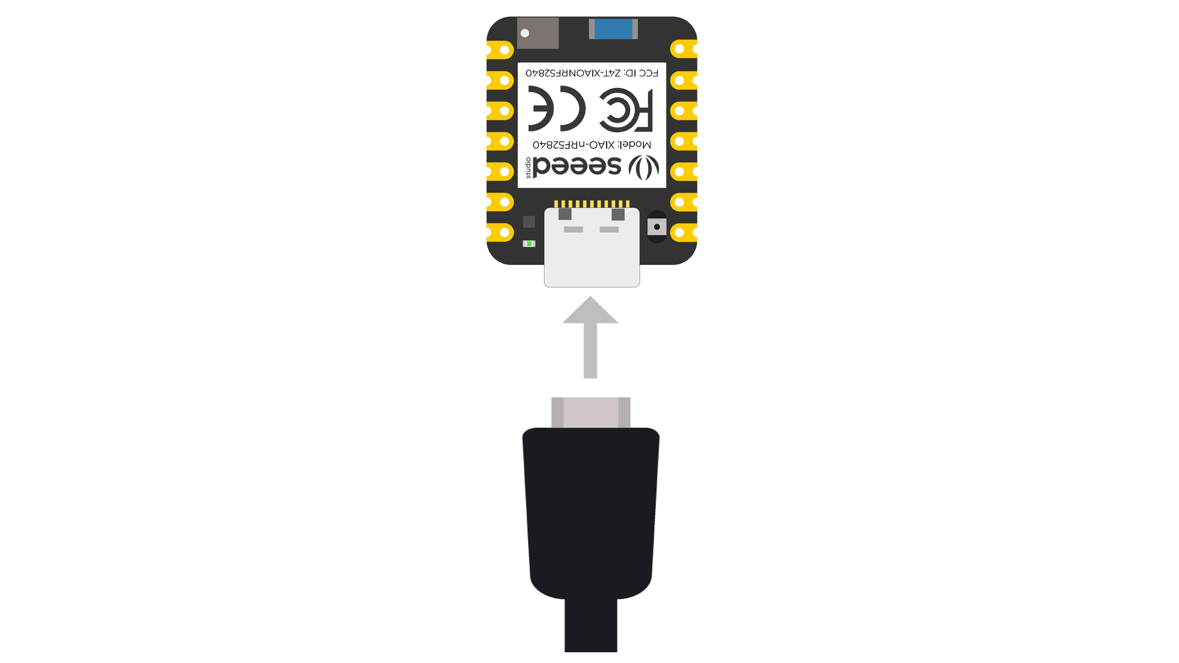
Connect the Seeed Studio XIAO nRF52840 (Sense) to your computer via a USB Type-C cable.
Software setup
Step 1. Download and Install the latest version of Arduino IDE according to your operating system
![]()
Step 2. Launch the Arduino application
Step 3. Add Seeed Studio XIAO nRF52840 (Sense) board package to your Arduino IDE
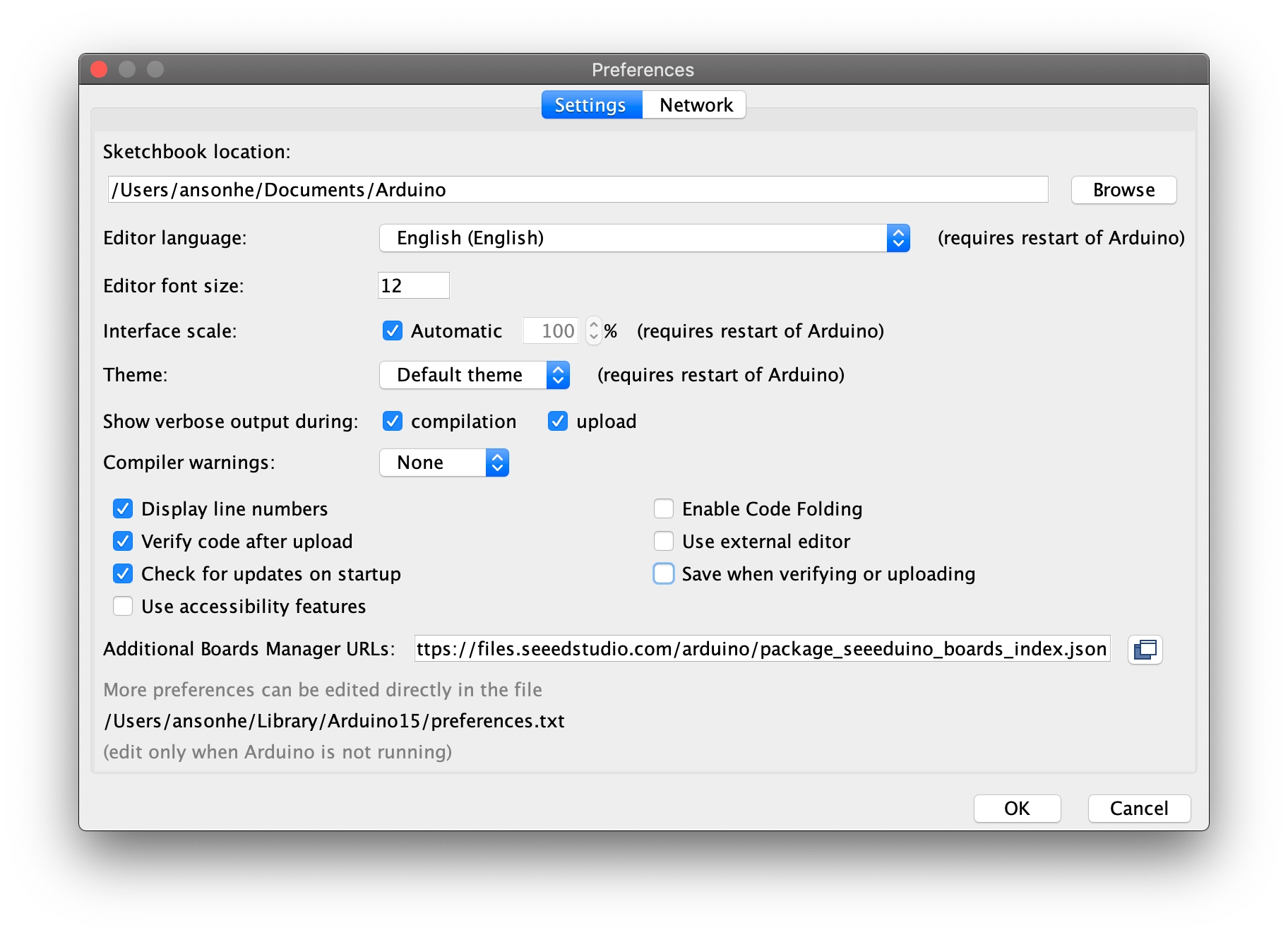
Navigate to File > Preferences, and fill "Additional Boards Manager URLs" with the url below: https://files.seeedstudio.com/arduino/package_seeeduino_boards_index.json
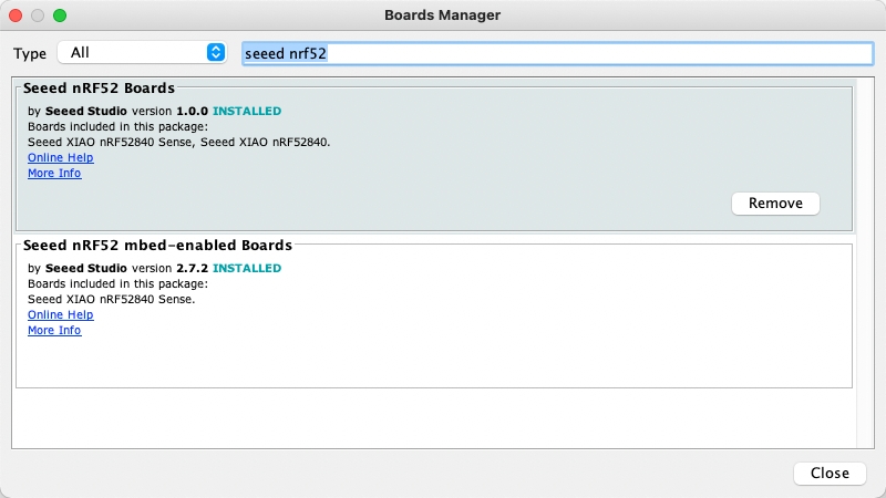
Navigate to Tools > Board > Boards Manager..., type the keyword "seeed nrf52" in the search box, select the latest version of the board you want, and install it. You can install both.
Step 4. Select your board and port
Board
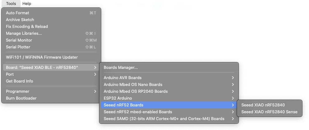
After installing the board package, navigate to Tools > Board and choose the board you want, continue to select "Seeed XIAO nRF52840 Sense". Now we have finished setting up the Seeed Studio XIAO nRF52840 (Sense) for Arduino IDE.
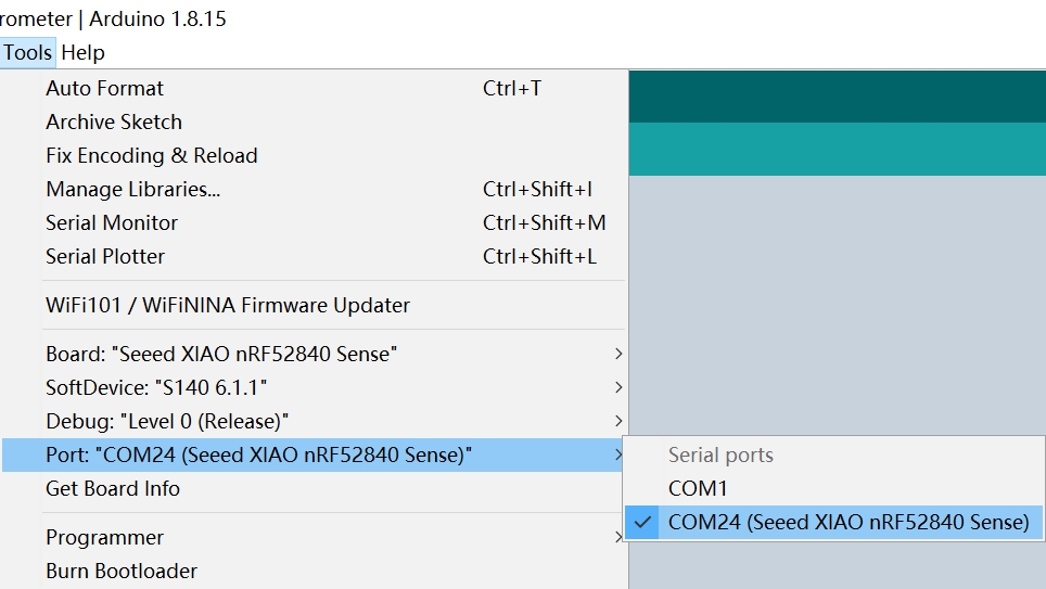
Port
Navigate to Tools > Port and select the serial port name of the connected Seeed Studio XIAO nRF52840 (Sense). This is likely to be COM3 or higher (COM1 and COM2 are usually reserved for hardware serial ports). The serial port of the connected Seeed Studio XIAO nRF52840 (Sense) usually contains parentheses that are written Seeed Studio XIAO nRF52840 for Seeed Studio XIAO nRF52840 or Seeed Studio XIAO nRF52840 Sense for Seeed Studio XIAO nRF52840 Sense.
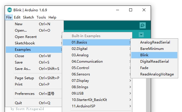
Step 5. Navigate to File > Examples > 01.Basics > Blink to open Blink example
Step 6. Click the Upload button to upload the Blink example code to the board
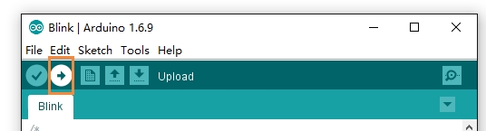
Once uploaded, you will see the built-in red LED blinking with a 1-second delay between each blink. This means the connection is successful and now you can explore more projects with the Seeed Studio XIAO nRF52840 (Sense)!
Playing with the built-in 3-in-one LED
Seeed Studio XIAO nRF52840 (Sense) has an onboard 3-in-one LED which is user-programmable. Now you will learn how to control the RGB colors one-by-one using Arduino!
You first have to understand that the behavior of this LED is not as usual when controlled by the code. The LED turns ON when we give a LOW signal and it turns OFF when we give a HIGH signal. This is because this LED is controlled by a common anode and will light up only with a low-level signal.
An example code would be:
Here, even though HIGH is used, the LED will be OFF. You need to replace HIGH with LOW to turn ON the LED.
Refer to the following pin mappings of the LEDs and use them in your codes:
Red LED = LED_BUILTIN or LED_RED
Blue LED = LED_BLUE
Green LED = LED_GREEN
Power Consumption Verification
The Seeed Studio XIAO nRF52840 is low power consumption and here we provide a method to verify. It is highly recommend to use the Seeed nRF52 Boards library here.
Step 1. Use JLink Downloader to flash the bootloader firmware for Seeed Studio XIAO nRF52840 (Sense).
Step 2. Use the
Seeed nRF52 Boardslibrary here.

Step 3. Upload the deep_sleep demo here and run it with Arduino
If you want to know about this example more detail inforation , Click Here
Battery Charging current
The battery charging current is selectable as 50mA or 100mA, where you can set Pin13 as high or low to change it to 50mA or 100mA. The low current charging current is at the input model set up as HIGH LEVEL and the high current charging current is at the output model set up as LOW LEVEL.
Low Charging Current
High Charging Current
Access the SWD Pins for Debugging and Reflashing Bootloader
Hardware Required
Jlink
Software Required
It is required to download the Segger software from the website.
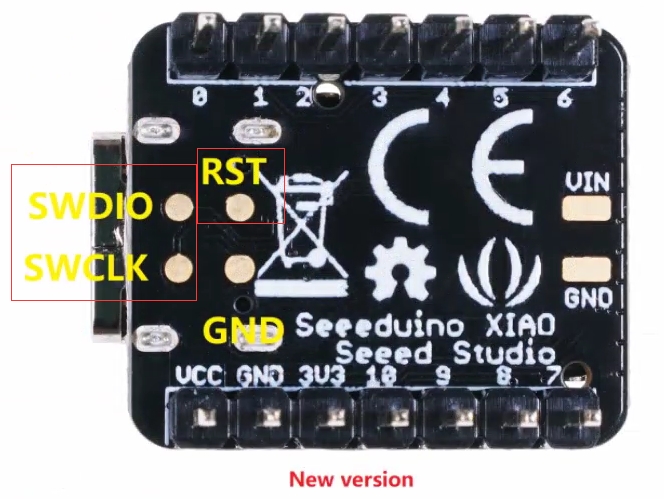
Step 1. Use Jlink to connect pins below:
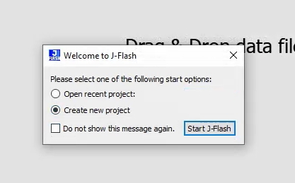
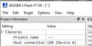
Step 2. Start the J-Flash and search nRF52840, creating a new project:
Step 3. Click "Target" and then select "Connect".
Step 4. Draw the bin or hex file to software. Then press F4 and F5 in that order. The reflashing is done.
FAQ
What are the considerations when using XIAO nRF52840 (Sense) for battery charging?
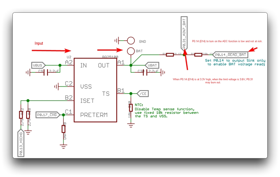
When P0.14 (D14) turns off the ADC function at a high level of 3.3V, P0.31 will be at the input voltage limit of 3.6V. There is a risk of burning out the P0.31 pin.
Currently for this issue, we recommend that users do not turn off the ADC function of P0.14 (D14) or set P0.14 (D14) to high during battery charging.
How does the green light behave when powered on?
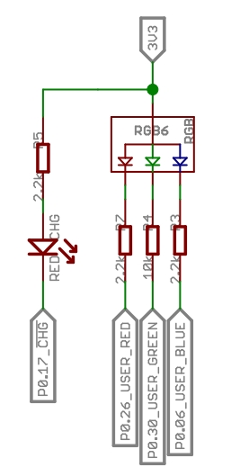
The P0.17 pin is used to control the green indicator light behavior, indicating the charging status:
Low level: when charging is in progress.
High level: when the battery is either not charging or fully charged.
When it is at a low level, the RED_CHG LED will light up.
For more details, check the PMIC datasheet: BQ25100 and XIAO nRF52840 datasheet.
Last updated
Was this helpful?