Waveshare 7 inch Capacitive Touch Screen with Case HDMI
Product Link
Introduction
7inch Capacitive Touch Screen LCD, HDMI interface, with a resolution of 800 × 480 and a capacitive touch panel, which supports Raspberry Pi and can also be used as a computer monitor.
Features
800 × 480 hardware resolution.
5-point capacitive touch control.
When used with Raspberry Pi, supports Raspberry Pi OS/Ubuntu/Kali and Retropie.
When used as a computer monitor, supports Windows 11/10/8.1/8/7.
Support backlight control, saving more power.
Working with PC
This LCD can support Windows 7/8/8.1/10/11 system.
How to use:
1) Turn on the backlight switch on the back of the LCD.
2) Connect the Touch interface of the LCD to the USB interface of the PC. Wait for a while, the windows will automatically recognize the touch function.
3) Connect the HDMI interface of the LCD to the HDMI interface of the PC.
Note: 1) When the computer is connected to several different displays at the same time, only this LCD can be used to control the cursor on the main display, so we recommended to set this LCD as the main display. 2) Some PCs do not support plug-and-play with HDMI devices. Generally, they can be used normally after restarting the system. 3) Some PCs may cause LCD flickering due to insufficient power supply through the USB interface. Generally, they can be used normally after connecting to an external 5V/2A power supply through the DC interface.
Working with Raspberry Pi
This LCD can support Raspberry Pi OS / Ubuntu / Kali and Retropie systems. When the LCD works on systems such as Raspberry Pi OS, the resolution must be set manually, otherwise, it will cause an abnormal display.
Please download the latest version of the image on the Raspberry Pi official website.
1) Download the compressed file to the PC, and unzip it to get the .img file.
2) Connect the TF card to the PC, and use SDFormatter software to format the TF card.
3) Open the Win32DiskImager software, select the system image downloaded in step 1, and click 'Write' to write the system image.
4) After the image has finished writing, open the config.txt file in the root directory of the TF card, add the following code at the end of config.txt, then save and quit the TF card safely.
5) Insert the TF card into the Raspberry Pi
6) Turn on the backlight switch on the back of the LCD.
7) Connect the Touch interface of the LCD to the USB interface of the Raspberry Pi.
8) Connect the HDMI interface of the LCD to the HDMI interface of the Raspberry Pi, power on the Raspberry Pi, and wait for a few seconds until the LCD displays normally.
EDID Sequence Parameters
If the system of the main control board can automatically recognize the EDID for display, there is no need to additionally set related timing parameters. Otherwise, you can refer to the following EDID settings:
32.00
800
128
480
45
40
48
13
3
108
68
0
0
Resources
3D Drawings
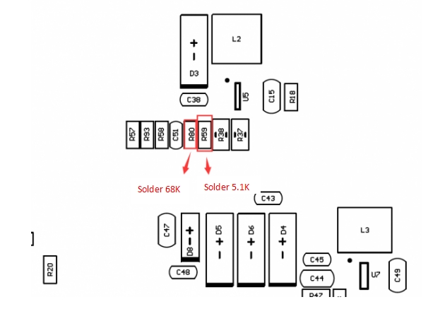
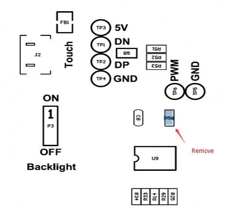
Note: We don't recommend you do any hardware modification, which may damage the LCD if you are not good at it. So be careful when you follow this manual.
Software
FAQ
Last updated
Was this helpful?


