Seeed Studio SenseCAP Card Tracker T1000-E for LoRaWAN
Product Link
Description
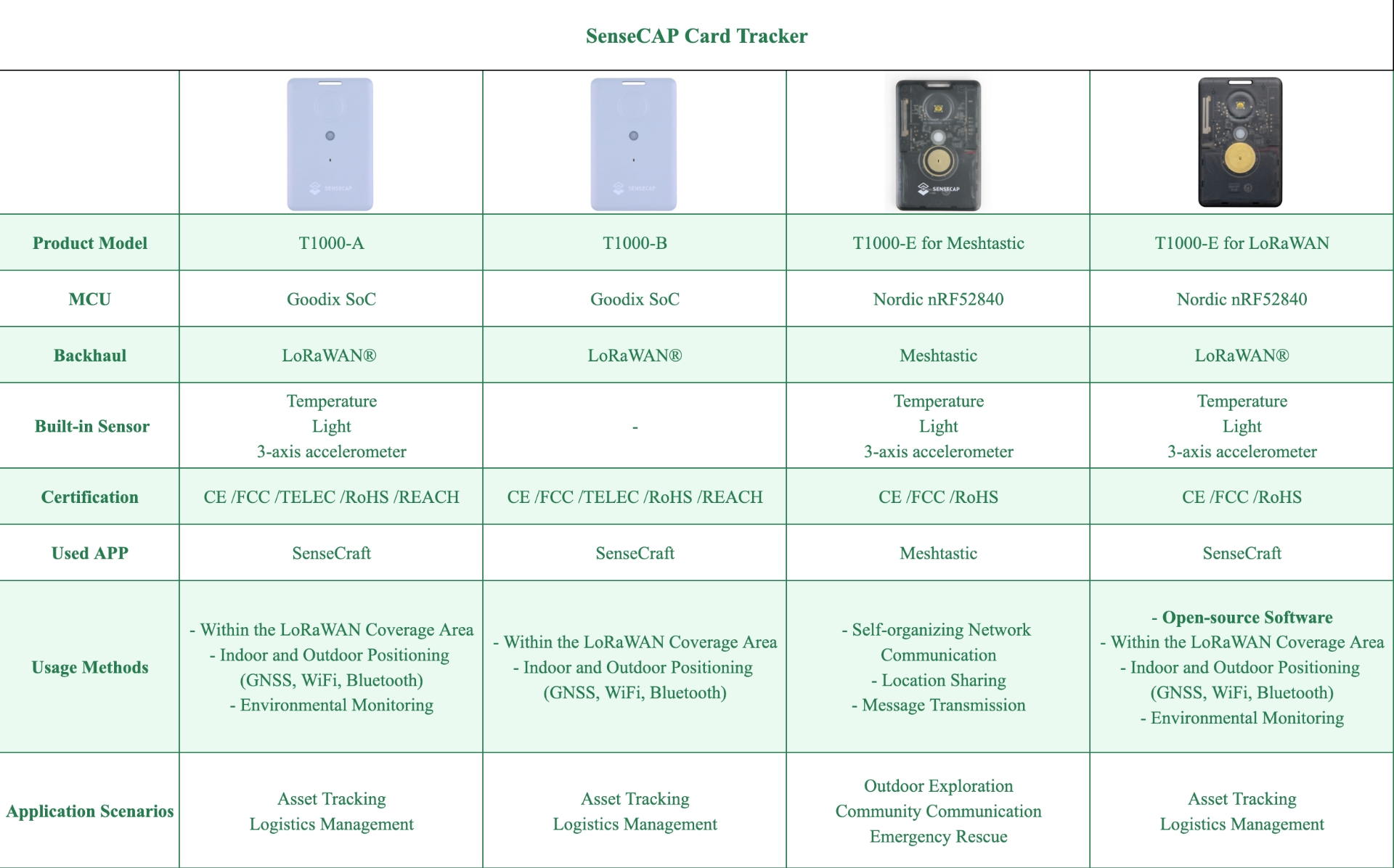
T1000-E for LoRaWAN comes with fully open-source firmware. To enhance the user experience, we provide demo firmware pre-installed on factory-produced devices. Users can explore the demo firmware for an initial experience and also develop your own custom firmware.
T1000 Series Version Comparison
Hardware
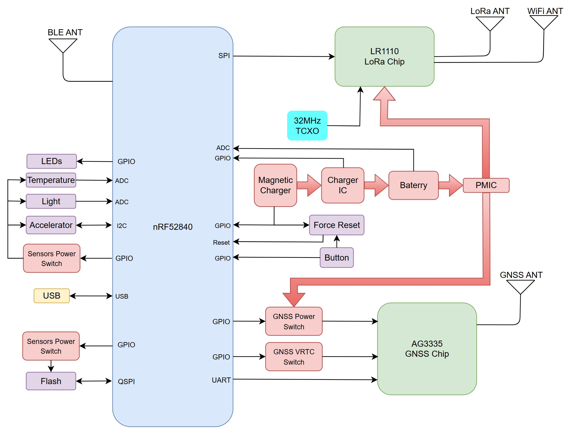
Diagram
Pin Descriptions
1
P0.00
XL1
Connection for 32.768 kHz crystal
2
P0.01
XL2
Connection for 32.768 kHz crystal
3
P0.02
Digital I/O
Analog input
Baterry level dectect
4
P0.03
Digital I/O
Analog input
Red LED IO
5
P0.04
Digital I/O
Analog input
VCC voltage dectect
6
P0.05
Digital I/O
Analog input
Charger insert dectect,must be configured as no pullup or pulldown
7
P0.06
Digital I/O
Key IO, must be configured as input_pulldown
8
P0.07
Digital I/O
LR1110 BUSY
9
P0.08
Digital I/O
AG3335 VRTC EN
10
P0.09
NFC input
NC
11
P0.10
NFC input
NC
12
P0.11
Digital I/O
SPI SCK
13
P0.12
Digital I/O
SPI CS
14
P0.13
Digital I/O
UART1 TX For AG3335
15
P0.14
Digital I/O
UART1 RX For AG3335
16
P0.15
Digital I/O
AG3335 RTC Interrupt
17
P0.16
Digital I/O
UART1 TX For debug
18
P0.17
Digital I/O
UART1 RX For debug
19
P0.18
Reset
Reset
20
P0.19
Digital I/O
QSPI Clock for FLASH
21
P0.20
Digital I/O
QSPI CS for FLASH
22
P0.21
Digital I/O
QSPI IO0 for FLASH
23
P0.22
Digital I/O
QSPI IO1 for FLASH
24
P0.23
Digital I/O
QSPI IO2 for FLASH
25
P0.24
Digital I/O
Green LED IO
26
P0.25
Digital I/O
Buzzer PWM
27
P0.26
Digital I/O
I2C SDA
28
P0.27
Digital I/O
I2C SCL
29
P0.28
Digital I/O
Analog input
NC
30
P0.29
Digital I/O
Analog input
Light Sensor ADC input
31
P0.30
Digital I/O
Analog input
NC
32
P0.31
Digital I/O
Analog input
Temperature Sensor ADC input
33
P1.00
Digital I/O
QSPI IO3 for FLASH
34
P1.01
Digital I/O
LR1110 DIO9
35
P1.02
Digital I/O
Accelerator Interrupt
36
P1.03
Digital I/O
Charger State
37
P1.04
Digital I/O
Charger Done
38
P1.05
Digital I/O
Buzzer Enable
39
P1.06
Digital I/O
Sensor VCC Enable
40
P1.07
Digital I/O
Accelerator Enable
41
P1.08
Digital I/O
SPI MISO
42
P1.09
Digital I/O
SPI MOSI
43
P1.10
Digital I/O
LR1110 RESET
44
P1.11
Digital I/O
AG3335 PWR EN
45
P1.12
Digital I/O
AG3335 SLEEP Interrupt
46
P1.13
Digital I/O
Flash Enable
47
P1.14
Digital I/O
AG3335 RESETB OUT
48
P1.15
Digital I/O
AG3335 Reset
Demo Firmware
Positioning Description
Location
Description
GNSS
Upload longitude and latitude info. (There is usually no GPS signal indoors, so it's recommended to test the device outdoors to get the location)
Wi-Fi
Upload the MAC address and RSSI info of the Wi-Fi AP.
Bluetooth
Upload the MAC address and RSSI info of the Bluetooth beacon.
Button
Button Action
Description
Long press for 3 seconds
Power on/off
Click button 3 times
Switch on/off Bluetooth
Double click
Switch on/off SOS alart
Click once
Upload location/battery/sensor data
LED
Red LED
Solid
Charging
Flash
Abnormal charging
Green LED
Solid
Device in DFU mode.
Reboot the device to exit DFU mode(Press and hold the button, then release it immediately after connecting the charging cable)
On 500ms/Off 1s
Bluetooth on
Breath
Joining LoRaWAN network
Quick flash for 2s and then off
Joined the LoRaWAN network successfully
Sensor Function
The SenseCAP T1000 Tracker is equipped with 3 sensors: Temperature sensor, Light sensor and 3-Axis Accelerometer. You can choose enable or disable these sensors:
note
When the sensors are turned on, the device will consume more power.
Sensor
Description
Temperature
Onboard independent temperature sensor.
here may be some temperature measurement delay here, because it is separated from the shell.
Range: -20 to 60℃; Accuracy: ± 1℃(min 0.5℃, max 1℃); Resolution: 0.1℃
Light
The light sensor is not the actual lumen value monitored, but a percentage of the light from dark to amount. Mainly can be used for anti-demolition monitoring and some light sensitive monitoring.
Range: 0 to 100%, (0% is dark, 100% is brightest)
3-Axis Accelerometer
By setting the value of acceleration, motion event and shock event are triggered.
Battery
Battery life depends on factors such as uplink interval, sensor usage, LoRa transmission distance, and operating temperature. Predicted battery life is based on a typical working environment (25°C) and serves as a reference. Actual battery life may vary.
EU868(1C/SF12)
Battery Life(day)
2.46
11.72
84.68
184.86
US915(1C/SF9)
Battery Life(day)
2.89
13.66
92.59
186.83
Get Started
Press the button for 3s to power on the device, a rising melody indicates that the device has been successfully powered on.
Connect via App
Step 1: Download
SenseCraftApp

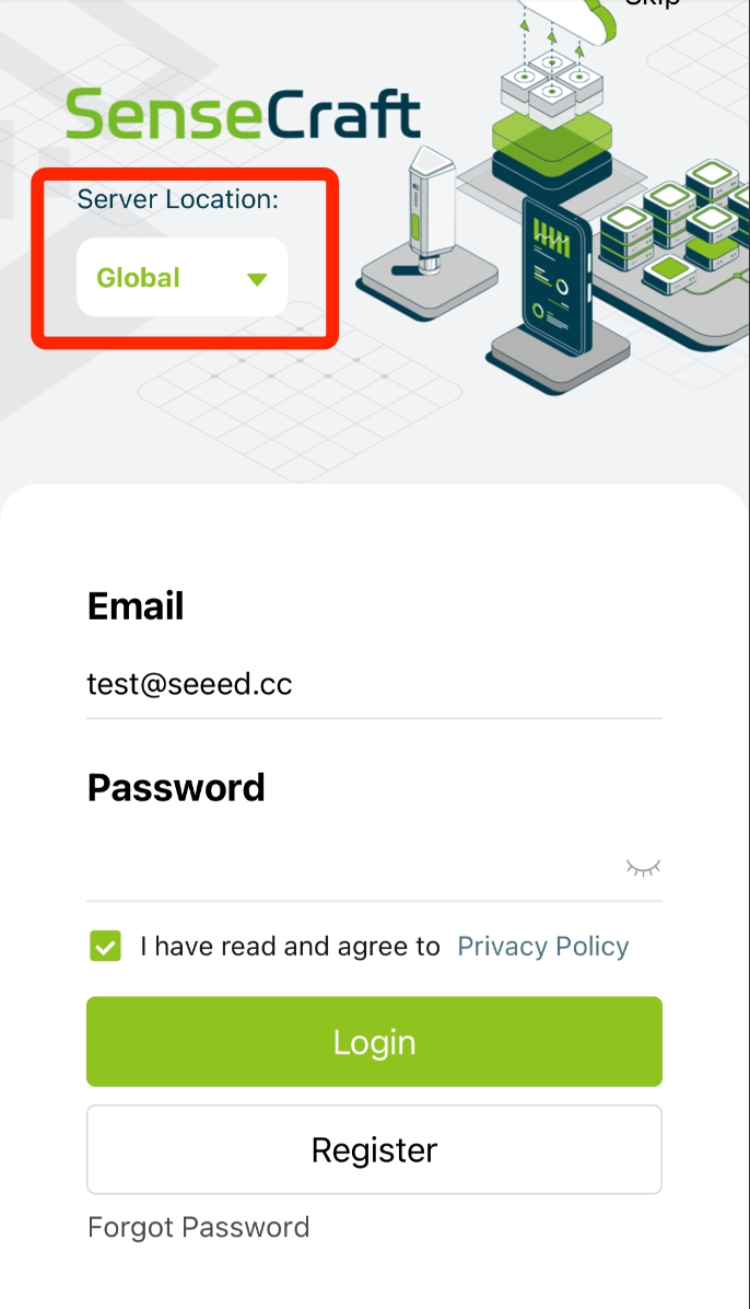
Login to the SenseCraft APP.
tip:
Select Server Location as Global.
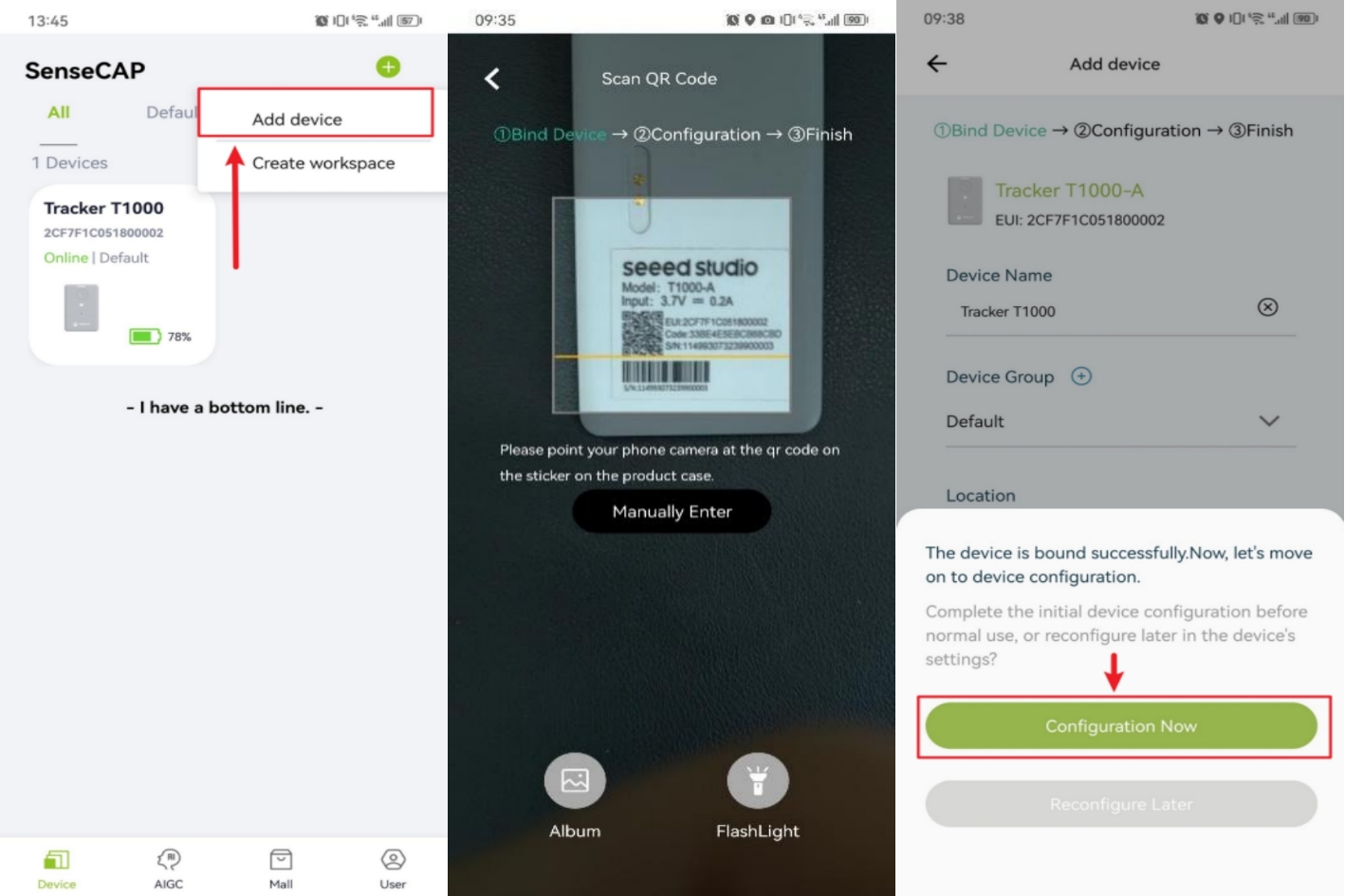
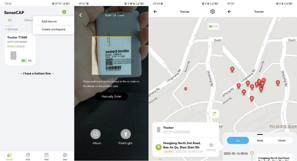
Step 2: Add Device
Click Add Device tab on the top right, then scan the QR code on the device label.
Configure the Device
Navigate to
User->Device Bluetooth Configurationpage.
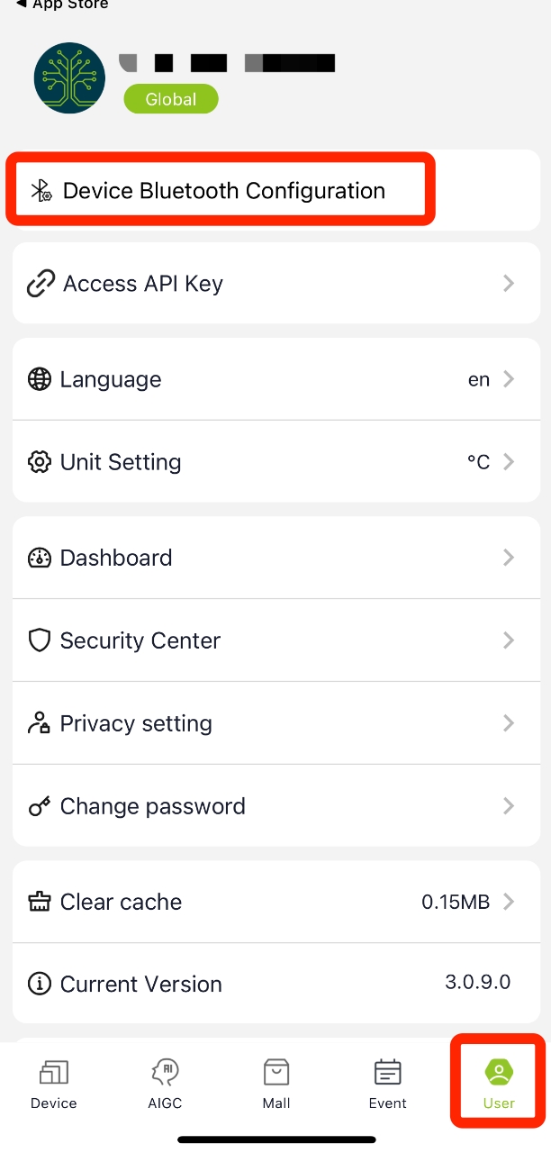
Click the button 3 times to enter the configuration mode. Device name: T1000-E xxxx(the last four digits of the MAC address).
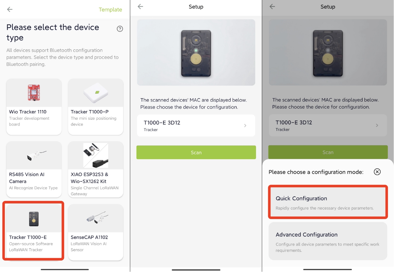
Quick Configuration
For quick start with the SenseCAP cloud, you can select Quick Configuration.
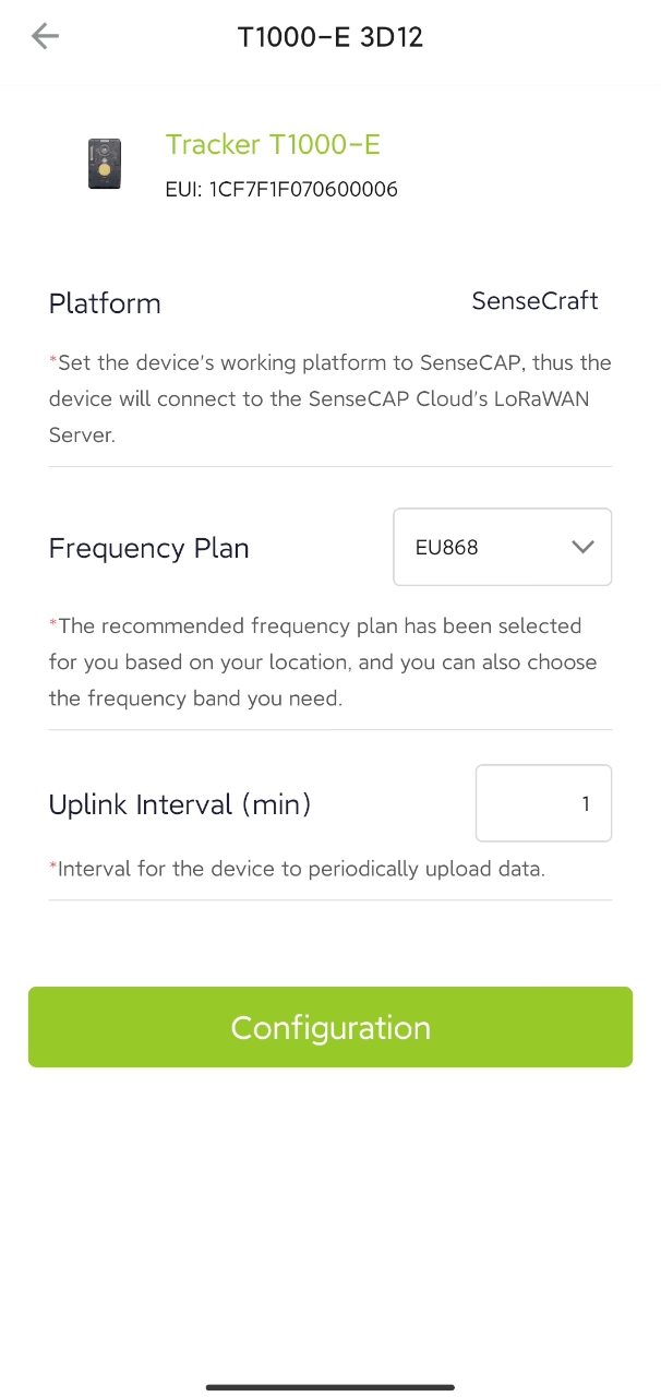
Configure the Frequency Plan according to your region, and set up the Uplink Interval you want.
Advanced Configuration
For advanced usage, please select Advanced Configuration.
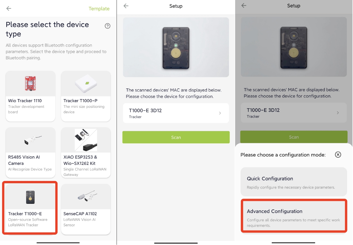
You can see the current device information, which includes the device EUI, hardware/software version, battery, etc.
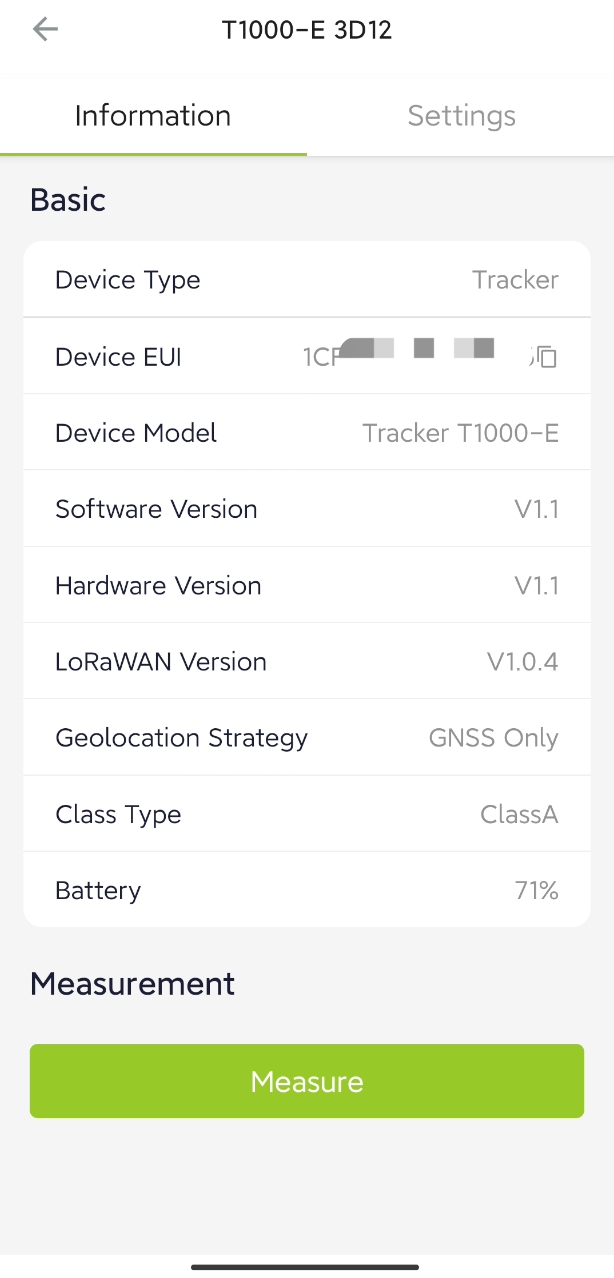
Navigate to Settings to set up the parameters.
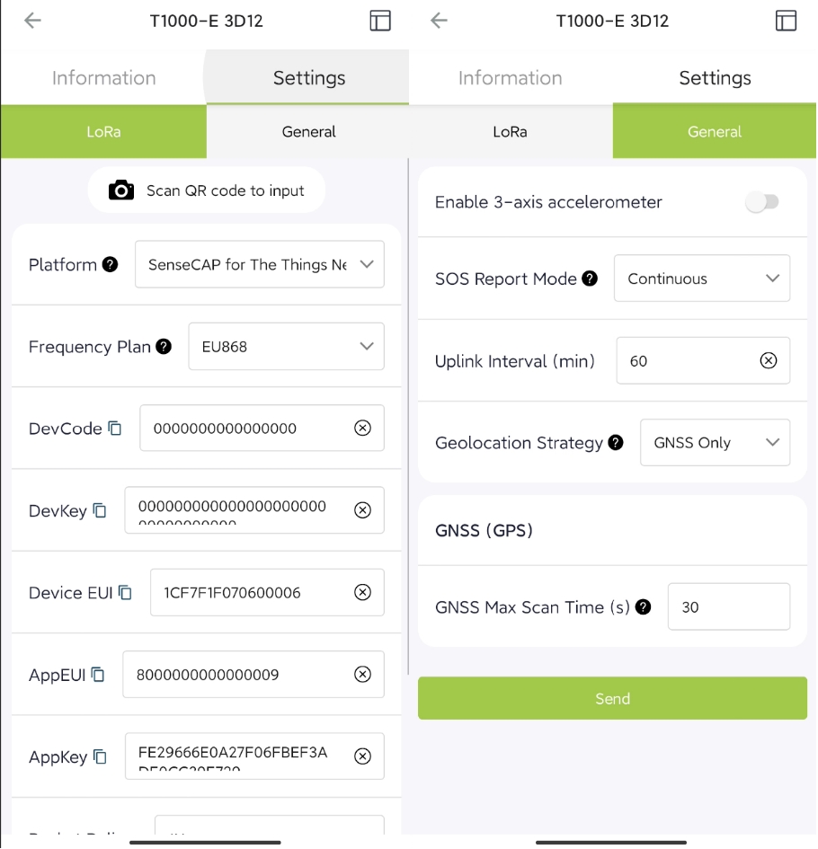
LoRa Setup
Platform
SenseCAP for The Things Network(by default)
A proprietary TTN server of SenseCAP. Out of the box when paired with a SenseCAP gateway.
SenseCAP for Helium
A private Helium console of SenseCAP.
Out of the box with SenseCAP Mate App and Portal.
Helium
Public Helium Server
The Things Network
Public TTN Server
Other Platform
Other LoRaWAN Network Server
Frequency Plan
EU868/US915/AU915/KR920/IN865/AS923-1/AS923-2/AS923-3/AS923-4
EU868 by default
Packet Policy
1C
Enable by default
LoRaWAN ADR
Enable by default
Enable by default
Restore LoRa Configuration
Enable by default
Enable by default
General Setup
3-axis accelerometer
Enable/Disable, disable by default
Upload the data of the 3-axis accelerometer
SOS Report Mode
Single(by default)
Upload data and report SOS event once. Buzzer alarm for 3 seconds
Continuous
Upload data and report SOS event every minute, ends after 30 times. Buzzer alarm for 30 seconds
Uplink Interval(min)
1-10080min, 60min by default
Upload data at intervals. The higher the frequency, the higher the power consumption
Geolocation Strategy
GNSS only(by default)
Uses only GPS satellite systems to determine the position
Wi-Fi only
Upload the MAC address and RSSI info of the Wi-Fi AP
Bluetooth only
Upload the MAC address and RSSI info of the Bluetooth beacon
GNSS + Wi-Fi
Uses GPS positioning first, if GPS fails, then uses Wi-Fi in one geolocation cycle
Bluetooth + GNSS
Uses Bluetooth positioning first, if Bluetooth fails, then uses GNSS in one geolocation cycle
Bluetooth + Wi-Fi
Uses Bluetooth positioning first, if Bluetooth fails, then uses Wi-Fi in one geolocation cycle
Bluetooth + Wi-Fi + GNSS
Use Bluetooth, Wi-Fi and GNSS for positioning in turn (switch to the next type of positioning after one type of positioning fails)
GNSS(GPS)
GNSS Max Scan Time(s)
10-120s, 30s by default
IBeacon Scan
Maximum number of BLE scans
3-5, 3 by default
Scan Timeout(s)
3-10s, 3s by default
Group UUID(Hex)
Set UUID Filter, up to 16bytes. Forexample, if set as '01 020304', it will filter beacons with thepattern'0102 03 04 xx xx xx ...'
Wi-Fi Scan
Maximum number of Wi-Fi scans
3-5, 3 by default
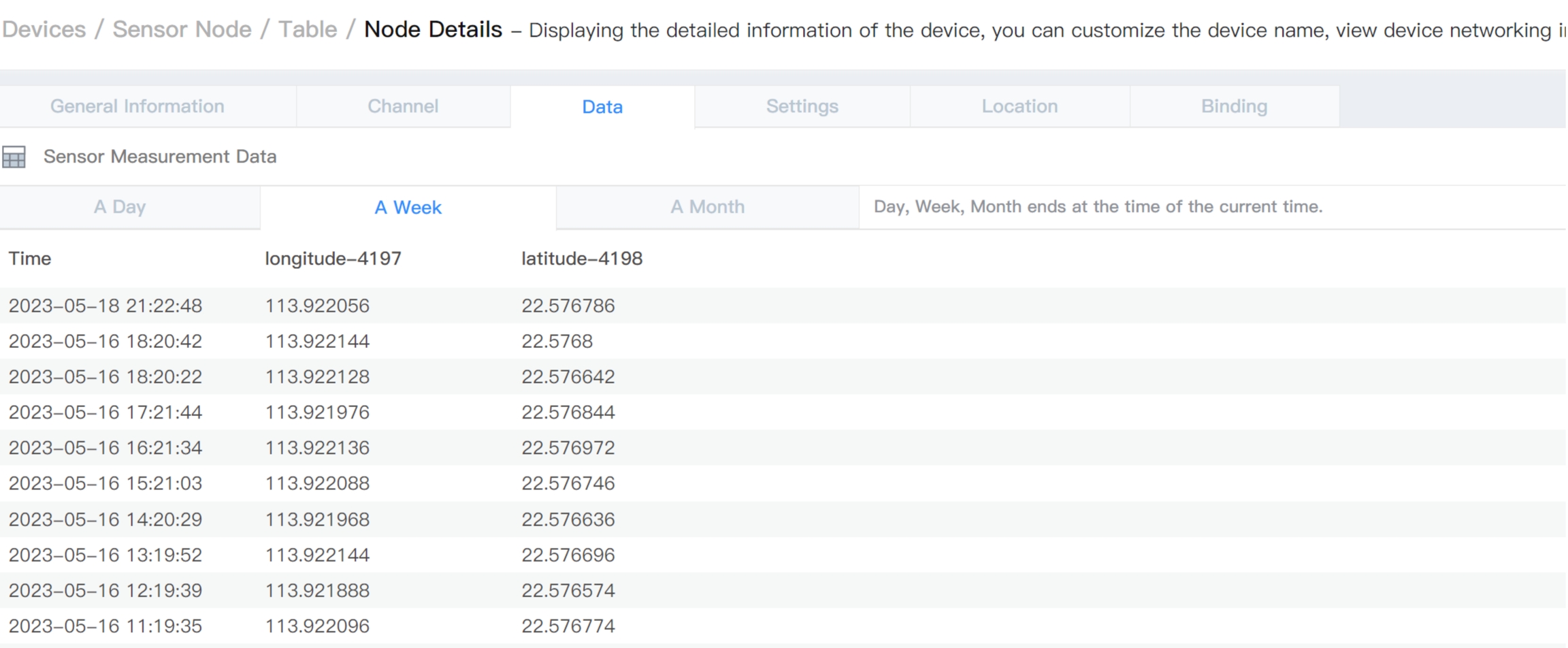
Device Data View
SenseCAP Mate App
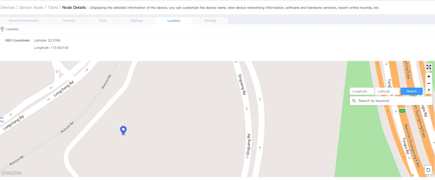
Check the Location on the APP.
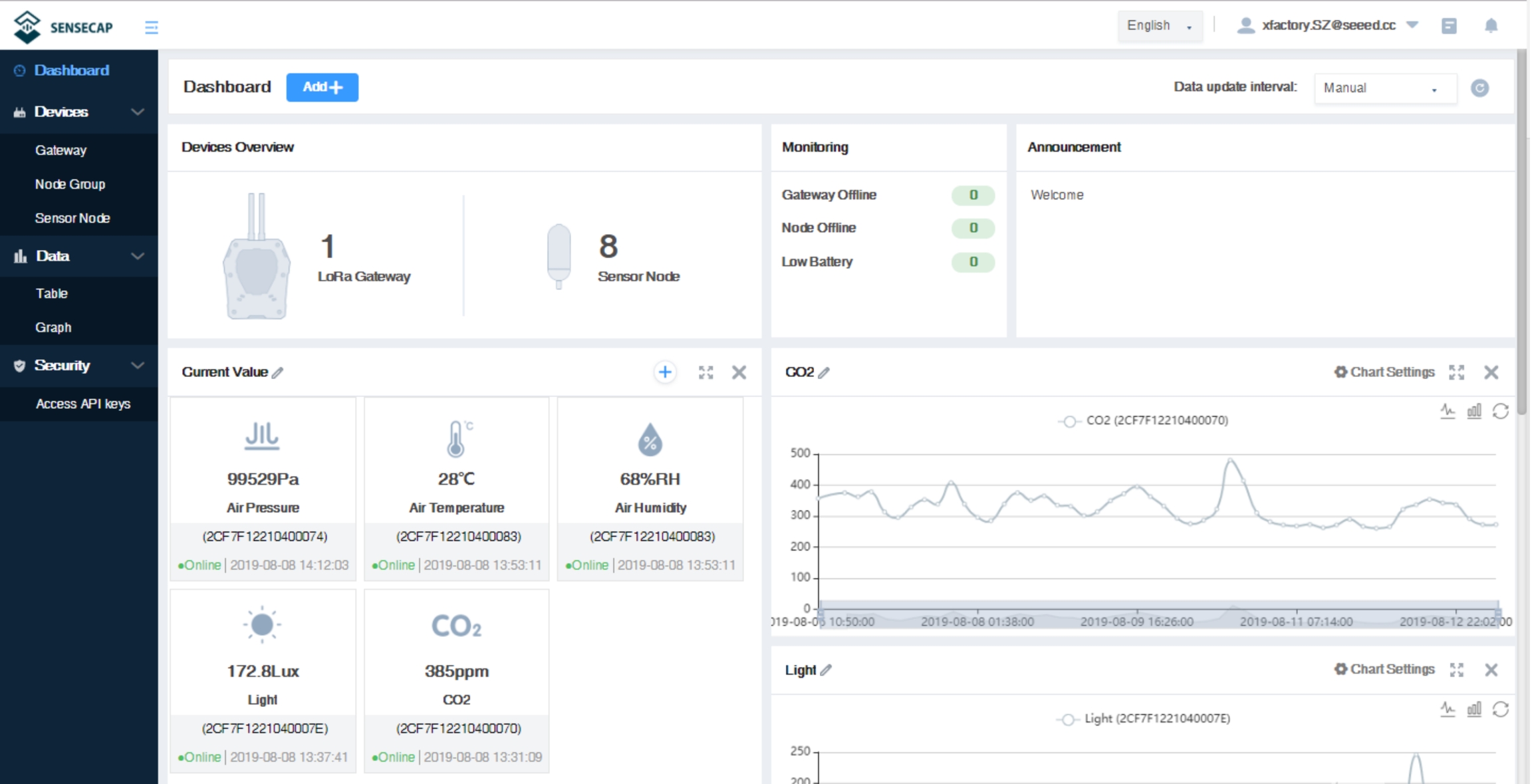
SenseCAP Portal
The main function of the SenseCAP Portal is to manage SenseCAP devices and store data. It is built on Azure, a secure and reliable cloud service from Microsoft. Users can apply for an account and bind all devices to this account. The SenseCAP Portal provides a web portal and API. The web portal includes Dashboard, Device Management, Data Management, and Access Key Management. The API is open to users for further development.
Dashboard: Including Device Overview, Announcement, Scene Data, and Data Chart, etc.
Device Management: Manage SenseCAP devices.
Data Management: Manage data, including Data Table and Graph section, providing methods to search for data.
Subaccount System: Register subaccounts with different permissions.
Access Key Management: Manage Access Key (to access API service), including Key Create, Key Update, and Key Check.
Device Data View
Log in SenseCAP Portal
If you have created an account through the APP, you can log in directly.
1) Select register account, enter email information, and click "register", the registered email will be sent to the user's mailbox
2) Open the "SenseCAP…"Email, click the jump link, fill in the relevant information, and complete the registration
3) Return to the login interface and complete the login
Check SenseCAP Portal User Guide for more details.
Last updated
Was this helpful?